Cybersecurity Gateway
Knowledge Objectives
- Describe the basic operation of computer networks and the internet, including common networking devices, routed and routing protocols, different types of area networks and topologies, and the Domain Name System (DNS).
- Explain the function of physical, logical, and virtual addressing in networking.
- Discuss IPv4 and IPv6 addressing and subnetting fundamentals.
- Discuss the OSI Reference Model and TCP/IP model including packet analysis, protocol and packet filtering, and TCP/IP encapsulation.
- Explain various network security models, concepts, and principles including perimeterbased security and the Zero Trust model.
- Discuss cloud and data center security design concepts including cloud computing security considerations and requirements, the role of virtualization in cloud computing, existing data security solution weaknesses, east-west traffic protection, and security in virtualized data centers.
- Describe network security technologies including firewalls, Intrusion Detection Systems and Intrusion Prevention Systems (IDS/IPS), web content filters, virtual private networks (VPNs), data loss prevention (DLP), Unified Threat Management (UTM), and security information and event management (SIEM).
- Explain cloud, virtualization, and storage security concepts and challenges.
- Discuss network operations concepts including traffic analysis, troubleshooting, and server and systems administration.
- Discuss directory services, network device optimization, and structured host and network troubleshooting.
- Describe IT Infrastructure Library (ITIL) concepts and help desk and technical support functions.
The Connected Globe
With more than four billion internet users worldwide in 2018, which represents well over half the world's population, the internet connects businesses, governments, and people across the globe. Our reliance on the internet will continue to grow, with nearly 30 billion devices and "things" – including autonomous vehicles, household appliances, wearable technology, and more – connecting to the internet of things (IoT) and more than 7.3 billion worldwide smartphone subscriptions each downloading 17 gigabytes (GB) of monthly data by 2023.
The NET: How things connect
In the 1960s, the U.S. Defense Advanced Research Project Agency (DARPA) created ARPANET, the precursor to the modern internet. ARPANET was the first packet switching network. A packet switching network breaks data into small blocks (packets), transmits each individual packet from node to node toward its destination, then reassembles the individual packets in the correct order at the destination.
Today, hundreds of millions of routers (discussed in Section 2.1.2) deliver Transmission Control Protocol/Internet Protocol (TCP/IP) packets using various routing protocols (discussed in Section 2.1.3) across local-area networks and wide-area networks (LANs and WANs, respectively, discussed in Section 2.1.4). The Domain Name System (DNS, discussed in Section 2.1.5) enables internet addresses, such as www.paloaltonetworks.com, to be translated into routable IP addresses.
Introduction to networking devices
Routers are physical or virtual devices that send data packets to destination networks along a network path using logical addresses (discussed in Section 2.2). Routers use various routing protocols (discussed in Section 2.1.3) to determine the best path to a destination, based on variables such as bandwidth, cost, delay, and distance. A wireless router combines the functionality of a router and a wireless access point (AP) to provide routing between a wired and wireless network. An AP is a network device that connects to a router or wired network and transmits a Wi-Fi signal so that wireless devices can connect to a wireless (or Wi-Fi) network. A wireless repeater rebroadcasts the wireless signal from a wireless router or AP to extend the range of a Wi-Fi network.
A hub (or concentrator) is a network device that connects multiple devices – such as desktop computers, laptop docking stations, and printers – on a local-area network (LAN). Network traffic that is sent to a hub is broadcast out of all ports on the hub, which can create network congestion and introduces potential security risks (broadcast data can be intercepted).
A switch is essentially an intelligent hub that uses physical addresses (discussed in Section 2.2) to forward data packets to devices on a network. Unlike a hub, a switch is designed to forward data packets only to the port that corresponds to the destination device. This transmission method (referred to as micro-segmentation) creates separate network segments and effectively increases the data transmission rates available on the individual network segments. Also, a switch can be used to implement virtual LANs (VLANs), which logically segregate a network and limit broadcast domains and collision domains.
Key Terms:
- A router is a network device that sends data packets to a destination network along a network path.
- A wireless repeater rebroadcasts the wireless signal from a wireless router or AP to extend the range of a Wi-Fi network.
- A hub (or concentrator) is a device used to connect multiple networked devices on a local-area network (LAN).
- A switch is an intelligent hub that forwards data packets only to the port associated with the destination device on a network.
- A virtual LAN (VLAN) is a logical network that is created within a physical LAN.
- A broadcast domain is the portion of a network that receives broadcast packets sent from a node in the domain.
- A collision domain is a network segment on which data packets may collide with each other during transmission.
Routed and routing protocols
Routed protocols, such as the Internet Protocol (IP), address packets with routing information that enables those packets to be transported across networks using routing protocols. IP is discussed further in Sections 2.2 and 2.2.1.
Routing protocols are defined at the Network layer of the OSI model (discussed in Section 2.3.1) and specify how routers communicate with one another on a network. Routing protocols can either be static or dynamic.
Key Terms:
- An Internet Protocol (IP) address is a 32-bit or 128-bit identifier assigned to a networked device for communications at the Network layer of the OSI model (discussed in Section 2.3.1) or the Internet layer of the TCP/IP model (discussed in Section 2.3.2).
A static routing protocol requires that routes be created and updated manually on a router or other network device. If a static route is down, traffic can't be automatically rerouted unless an alternate route has been configured. Also, if the route is congested, traffic can't be automatically rerouted over the less congested alternate route. Static routing is practical only in very small networks or for very limited, special-case routing scenarios (for example, a destination that's reachable only via a single router or when used as a backup route). However, static routing has low bandwidth requirements (routing information isn't broadcast across the network) and some built-in security (users can only get to destinations that are specified in statically defined routes).
A dynamic routing protocol can automatically learn new (or alternate) routes and determine the best route to a destination. The routing table is updated periodically with current routing information. Dynamic routing protocols are further classified as:
Distance-vector. A distance-vector protocol makes routing decisions based on two factors: the distance (hop count or other metric) and vector (the egress router interface). It periodically informs its peers and/or neighbors of topology changes. Convergence, the time required for all routers in a network to update their routing tables with the most current information (such as link status changes), can be a significant problem for distance-vector protocols. Without convergence, some routers in a network may be unaware of topology changes, which causes the router to send traffic to an invalid destination. During convergence, routing information is exchanged between routers, and the network slows down considerably. Convergence can take several minutes in networks that use distance-vector protocols.
Routing Information Protocol (RIP) is an example of a distance-vector routing protocol that uses hop count as its routing metric. To prevent routing loops, in which packets effectively get stuck bouncing between various router nodes, RIP implements a hop limit of 15, which limits the size of networks that RIP can support. After a data packet crosses 15 router nodes (hops) between a source and a destination, the destination is considered unreachable. In addition to hop limits, RIP employs four other mechanisms to prevent routing loops:
- Split horizon. Prevents a router from advertising a route back out through the same interface from which the route was learned.
- Triggered updates. When a change is detected the update gets sent immediately instead of waiting 30 seconds to send a RIP update.
- Route poisoning. Sets the hop count on a bad route to 16, which effectively advertises the route as unreachable.
- Holddown timers. Causes a router to start a timer when the router first receives information that a destination is unreachable. Subsequent updates about that destination will not be accepted until the timer expires. This timer also helps avoid problems associated with flapping. Flapping occurs when a route (or interface) repeatedly changes state (up, down, up, down) over a short period of time.
Link-state. A link-state protocol requires every router to calculate and maintain a complete map, or routing table, of the entire network. Routers that use a link-state protocol periodically transmit updates that contain information about adjacent connections, or link states, to all other routers in the network. Link-state protocols are compute-intensive, but they can calculate the most efficient route to a destination. They consider numerous factors such as link speed, delay, load, reliability, and cost (an arbitrarily assigned weight or metric). Convergence occurs very rapidly (within seconds) with link-state protocols.
Open Shortest Path First (OSPF) is an example of a link-state routing protocol that is often used in large enterprise networks. OSPF routes network traffic within a single autonomous system (AS). OSPF networks are divided into areas identified by 32-bit area identifiers. Area identifiers can (but don't have to) correspond to network IP addresses and can duplicate IP addresses without conflicts.
Path-vector. A path-vector protocol is similar to a distance-vector protocol, but without the scalability issues associated with limited hop counts in distance-vector protocols. Each routing table entry in a path-vector protocol contains path information that gets dynamically updated.
Key Terms:
- Convergence is the time required for all routers in a network to update their routing tables with the most current routing information about the network.
- Hop count generally refers to the number of router nodes that a packet must pass through to reach its destination.
- An autonomous system (AS) is a group of contiguous IP address ranges under the control of a single internet entity. Individual autonomous systems are assigned a 16-bit or 32-bit AS number (ASN) that uniquely identifies the network on the Internet. ASNs are assigned by the Internet Assigned Numbers Authority (IANA).
- Border Gateway Protocol (BGP) is an example of a path-vector protocol used between separate autonomous systems. BGP is the core protocol used by Internet Service Providers (ISPs), network service providers (NSPs), and on very large private IP networks.
Area networks and topologies
Most computer networks are broadly classified as either local-area networks (LANs) or widearea networks (WANs).
A local-area network (LAN) is a computer network that connects end-user devices such as laptop and desktop computers, servers, printers, and other devices so that applications, databases, files, file storage, and other networked resources can be shared among authorized users on the LAN. A LAN operates across a relatively small geographic area, such as a floor, a building, or a group of buildings, typically at speeds of up to 10 megabits per second (Mbps - Ethernet), 100Mbps (Fast Ethernet), 1,000Mbps (or 1 gigabit per second [1Gbps] – Gigabit Ethernet) on wired networks and 11Mbps (802.11b), 54Mbps (802.11a and g), 450Mbps (802.11n), 1.3Gbps (802.11ac), and 14Gbps (802.11ax – theoretical) on wireless networks. A LAN can be wired, wireless, or a combination of wired and wireless. Examples of networking equipment commonly used in LANs include bridges, hubs, repeaters, switches, and wireless access points (APs).
Key Terms:
- A local-area network (LAN) is a computer network that connects laptop and desktop computers, servers, printers, and other devices so that applications, databases, files and file storage, and other networked resources can be shared across a relatively small geographic area, such as a floor, a building, or a group of buildings.
- A bridge is a wired or wireless network device that extends a network or joins separate network segments.
- A repeater is a network device that boosts or re-transmits a signal to physically extend the range of a wired or wireless network.
Two basic network topologies (and many variations) are commonly used in LANs:
- Star. Each node on the network is directly connected to a switch, hub, or concentrator, and all data communications must pass through the switch, hub, or concentrator. The switch, hub, or concentrator can thus become a performance bottleneck or single point of failure in the network. A star topology is ideal for practically any size environment and is the most commonly used basic LAN topology. A star topology is also easy to install and maintain, and network faults are easily isolated without affecting the rest of the network.
- Mesh. All nodes are interconnected to provide multiple paths to all other resources. A mesh topology may be used throughout the network or only for the most critical network components, such as routers, switches, and servers, to eliminate performance bottlenecks and single points of failure.
Other once-popular network topologies, such as ring and bus, are rarely found in modern networks.
Key Terms:
- In a ring topology, all nodes are connected in a closed loop that forms a continuous ring. In a ring topology, all communication travels in a single direction around the ring. Ring topologies were common in token ring networks.
- In a bus (or linear bus) topology, all nodes are connected to a single cable (the backbone) that is terminated on both ends. In the past, bus networks were commonly used for very small networks because they were inexpensive and relatively easy to install, but today bus topologies are rarely used. The cable media has physical limitations (the cable length), the backbone is a single point of failure (a break anywhere on the network affects the entire network), and tracing a fault in a large network can be extremely difficult.
- A wide-area network (WAN) is a computer network that connects multiple LANs or other WANs across a relatively large geographic area, such as a small city, a region or country, a global enterprise network, or the entire planet (for example, the internet).
- A wide-area network (WAN) is a computer network that connects multiple LANs or other WANs across a relatively large geographic area, such as a small city, a region or country, a global enterprise network, or the entire planet (for example, the internet).
A WAN connects networks using telecommunications circuits and technologies such as broadband cable, digital subscriber line (DSL), fiber optic, optical carrier (for example, OC-3), and T-carrier (for example, T-1), at various speeds typically ranging from 256Kbps to several hundred megabits per second. Examples of networking equipment commonly used in WANs include access servers, Channel Service Units/Data Service Units (CSUs/DSUs), firewalls, modems, routers, virtual private network (VPN) gateways, and WAN switches.
The hierarchical internetworking model is a best practice network design, originally proposed by Cisco, that comprises three layers:
- Access. User endpoints and servers connect to the network at this layer, typically via network switches. Switches at this layer may perform some Layer 3 (discussed in Section 2.3.1) functions and may also provide electrical power via power over Ethernet (PoE) ports to other equipment connected to the network, such as wireless APs or Voice over IP (VoIP) phones.
- Distribution. This layer performs any compute-intensive routing and switching functions on the network such as complex routing, filtering, and Quality of Service (QoS). Switches at this layer may be Layer 7 (discussed in Section 2.3.1) switches and connect to lowerend Access layer switches and higher-end Core layer switches.
- Core. This layer is responsible for high-speed routing and switching. Routers and switches at this layer are designed for high-speed packet routing and forwarding.
Key Terms:
- Broadband cable is a type of high-speed internet access that delivers different upload and download data speeds over a shared network medium. The overall speed varies depending on the network traffic load from all the subscribers on the network segment.
- Digital subscriber line (DSL) is a type of high-speed internet access that delivers different upload and download data speeds. The overall speed depends on the distance from the home or business location to the provider's central office (CO).
- Fiber optic technology converts electrical data signals to light and delivers constant data speeds in the upload and download directions over a dedicated fiber optic cable medium. Fiber optic technology is much faster and more secure than other types of network technology.
- Optical carrier is a specification for the transmission bandwidth of digital signals on Synchronous Optical Networking (SONET) fiber optic networks. Optical carrier transmission rates are designated by the integer value of the multiple of the base rate (51.84Mbps). For example, OC-3 designates a 155.52Mbps (3 x 51.84) network and OC-192 designates a 9953.28Mbps (192 x 51.84) network.
- T-carrier is a full-duplex digital transmission system that uses multiple pairs of copper wire to transmit electrical signals over a network. For example, a T-1 circuit consists of two pairs of copper wire – one pair transmits, the other pair receives – that are multiplexed to provide a total of 24 channels, each delivering 64Kbps of data, for a total bandwidth of 1.544Mbps.
- Power over Ethernet (PoE) is a network standard that provides electrical power to certain network devices over Ethernet cables.
- Voice over IP (VoIP) or IP telephony is technology that provides voice communication over an Internet Protocol (IP)-based network.
- Quality of Service (QoS) is the overall performance of specific applications or services on a network including error rate, bit rate, throughput, transmission delay, availability, and jitter. QoS policies can be configured on certain network and security devices to prioritize certain traffic, such as voice or video, over other, less performance-intensive traffic.
In addition to LANs and WANs, many other types of area networks are used for different purposes:
- Campus area networks (CANs) and wireless campus area networks (WCANs) connect multiple buildings in a high-speed network (for example, across a corporate or university campus).
- Metropolitan area networks (MANs) and wireless metropolitan area networks (WMANs) extend networks across a relatively large area, such as a city.
- Personal area networks (PANs) and wireless personal area networks (WPANs) connect an individual's electronic devices – such as laptop computers, smartphones, tablets, virtual personal assistants (for example, Amazon Alexa, Apple Siri, Google Assistant, and Microsoft Cortana), and wearable technology – to each other or to a larger network.
- Storage area networks (SANs) connect servers to a separate physical storage device (typically a disk array).
- Value-added networks (VANs) are a type of extranet that allows businesses within an industry to share information or integrate shared business processes.
- Virtual local-area networks (VLANs) segment broadcast domains in a LAN, typically into logical groups (such as business departments). VLANs are created on network switches.
- Wireless local-area networks (WLANs), also known as Wi-Fi networks, use wireless access points (APs) to connect wireless-enabled devices to a wired LAN.
- Wireless wide-area networks (WWANs) extend wireless network coverage over a large area, such as a region or country, typically using mobile cellular technology.
Domain Name System (DNS)
The Domain Name System (DNS) is a distributed, hierarchical internet database that maps fully qualified domain names (FQDNs) for computers, services, and other resources – such as a website address (also known as a uniform resource locator, or URL) – to IP addresses (discussed in Sections 2.2 and 2.2.1), similar to how a contact list on a smartphone maps the names of businesses and individuals to phone numbers. To create a new domain name that will be accessible via the internet, you must register your unique domain name with a domain name registrar, such as GoDaddy or Network Solutions, similar to listing a new phone number in a phone directory. DNS is critical to the operation of the internet.
Key Terms:
- The Domain Name System (DNS) is a hierarchical distributed database that maps the fully qualified domain name (FQDN) for computers, services, or any resource connected to the Internet or a private network to an IP address.
- A fully qualified domain name (FQDN) is the complete domain name for a specific computer, service, or resource connected to the internet or a private network.
- A domain name registrar is an organization that is accredited by a top-level domain (TLD) registry to manage domain name registrations.
- A root name server is the authoritative name server for a DNS root zone. Worldwide, 13 root name servers (actually 13 networks comprising hundreds of root name servers) are configured, named a.root-servers.net through m.root-servers.net. DNS servers are typically configured with a root hints file that contains the names and IP addresses of the root servers.
A host (such as a web browser on a desktop computer) on a network that needs to connect to another host (such as a web server on the internet) must first translate the name of the destination host from its URL to an IP address. The connecting host (the DNS client) sends a DNS request to the IP address of the DNS server that is specified in the network configuration of the DNS client. If the DNS server is authoritative for the destination domain, the DNS server resolves the IP address of the destination host and answers the DNS request from the DNS client. For example, you are attempting to connect to an intranet server on your internal network from the desktop computer in your office. If the DNS server address that is configured on your computer is an internal DNS server that is authoritative for your intranet domain, the DNS server resolves the IP address of the intranet server. Your computer then encapsulates the resolved destination IP address in the Hypertext Transfer Protocol (HTTP) or Hypertext Transfer Protocol Secure (HTTPS) request packets that are sent to the intranet server.
If a DNS server is not authoritative for the destination domain, for example, an internet website address, then the DNS server performs a recursive query (if it is configured to perform recursive queries) to obtain the IP address of the authoritative DNS server and sends the original DNS request to the authoritative DNS server. This process is a top-down process in which the DNS server first consults its root hints file and queries a root name server to identify the authoritative DNS server for the TLD (for example, .com) associated with the DNS query. The DNS server then queries the TLD server to identify the authoritative server for the specific domain that is being queried (for example, paloaltonetworks.com). This process continues until the authoritative server for the FQDN is identified and queried. The recursive DNS server then answers the original DNS client's request with the DNS information from the authoritative DNS server.
The basic DNS record types are:
- A (IPv4) or AAAA (IPv6) (Address). Maps a domain or subdomain to an IP address or multiple IP addresses
- CNAME (Canonical Name). Maps a domain or subdomain to another hostname
- MX (Mail Exchanger). Specifies the hostname or hostnames of email servers for a domain
- PTR (Pointer). Points to a CNAME; commonly used for reverse DNS lookups that map an IP address to a host in a domain or subdomain
- SOA (Start of Authority). Specifies authoritative information about a DNS zone such as primary name server, email address of the domain administrator, and domain serial number
- NS (Name Server). The NS record specifies an authoritative name server for a given host
- TXT (Text). Stores text-based information
Key Terms:
- A top-level domain (TLD) is the highest level domain in DNS, represented by the last part of a FQDN (for example, .com, or .edu). The most commonly used TLDs are generic top-level domains (gTLD) such as .com, edu, .net, and .org, and country-code top-level domains (ccTLD) such as .ca and .us.
- An authoritative DNS server is the system of record for a given domain.
- An intranet is a private network that provides information and resources – such as a company directory, human resources policies and forms, department or team files, and other internal information – to an organization's users. Like the internet, an intranet uses the HTTP and/or HTTPS protocols, but access to an intranet is typically restricted to an organization's internal users. Microsoft SharePoint is a popular example of intranet software.
- Hypertext Transfer Protocol (HTTP) is an application protocol used to transfer data between web servers and web browsers.
- Hypertext Transfer Protocol Secure (HTTPS) is a secure version of HTTP that uses Secure Sockets Layer (SSL) or Transport Layer Security (TLS) encryption.
- A recursive DNS query is performed (if the DNS server allows recursive queries) when a DNS server is not authoritative for a destination domain. The nonauthoritative DNS server obtains the IP address of the authoritative DNS server for the destination domain and sends the original DNS request to that server to be resolved.
Physical, Logical, and Virtual Addressing
Physical, logical, and virtual addressing in computer networks requires a basic understanding of decimal (base10), binary (base2), and hexadecimal (base16) numbering (see Table 2-1).
The decimal (base10) numbering system is, of course, what we all are taught in school. It comprises the numerals 0 through 9. After the number 9, we add a digit ("1") in the "tens" position and begin again at zero in the "ones" position, thereby creating the number 10. Humans use the decimal numbering system, quite literally, because we have ten fingers, so a base10 numbering systems is easiest for humans to understand.
Table 2-1: Decimal, Hexadecimal, and Binary Notation
| Decimal | Hexadecimal | Binary |
| 0 | 0 | 0000 |
| 1 | 1 | 0001 |
| 2 | 2 | 0010 |
| 3 | 3 | 0011 |
| 4 | 4 | 0100 |
| 5 | 5 | 0101 |
| 6 | 6 | 0110 |
| 7 | 7 | 0111 |
| 8 | 8 | 1000 |
| 9 | 9 | 1001 |
| 10 | A | 1010 |
| 11 | B | 1011 |
| 12 | C | 1100 |
| 13 | D | 1101 |
| 14 | E | 1110 |
| 15 | F | 1111 |
A binary (base2) numbering system comprises only two digits – 1 ("on") and 0 ("off"). Binary numbering is used in computers and networking because they use electrical transistors (rather than fingers, like humans) to count. The basic function of a transistor is a gate – when electrical current is present, the gate is closed ("1" or "on"). When no electrical current is present, the gate is open ("0" or "off"). With only two digits, a binary numbering system increments to the next position more frequently than a decimal numbering system. For example, the decimal number one is represented in binary as "1," number two is represented as "10," number three is represented as "11," and number four is represented as "100."
A hexadecimal (base16) numbering system comprises 16 digits (0 through 9, and A through F). Hexadecimal numbering is used because it is more convenient to represent a byte (which consists of 8 bits) of data as two digits in hexadecimal, rather than eight digits in binary. The decimal numbers 0 through 9 are represented as in hexadecimal "0" through "9," respectively. However, the decimal number 10 is represented in hexadecimal as "A," the number 11 is represented as "B," the number 12 is represented as "C," the number 13 is represented as "D," the number 14 is represented as "E," and the number 15 is represented as "F." The number 16 then increments to the next numeric position, represented as "10."
The physical address of a network device, known as a media access control (MAC) address (also referred to as a burned-in address [BIA] or hardware address), is used to forward traffic on a local network segment. The MAC address is a unique 48-bit identifier assigned to the network interface controller (NIC) of a device. If a device has multiple NICs, each NIC must have a unique MAC address. The MAC address is usually assigned by the device manufacturer and is stored in the device read-only memory (ROM) or firmware. MAC addresses are typically expressed in hexadecimal format with a colon or hyphen separating each 8-bit section. An example of a 48bit MAC address is:
00:40:96:9d:68:16
The logical address of a network device, such as an IP address, is used to route traffic from one network to another. An IP address is a unique 32-bit or 128-bit (IPv4 and IPv6, respectively) address assigned to the NIC of a device. If a device has multiple NICs, each NIC may be assigned a unique IP address or multiple NICs may be assigned a virtual IP address to enable bandwidth aggregation or failover capabilities. IP addresses are statically or dynamically (most commonly using the Dynamic Host Configuration Protocol, or DHCP) assigned, typically by a network administrator or network service provider. IPv4 addresses are usually expressed in dotted decimal notation with a dot separating each decimal section (known as an octet). An example of an IPv4 address is:
192.168.0.1
IPv6 addresses are typically expressed in hexadecimal format (32 hexadecimal numbers grouped into eight blocks) with a colon separating each block of four hexadecimal digits (known as a hextet). An example of an IPv6 address is:
2001:0db8:0000:0000:0008:0800:200c:417a
IPv4 and IPv6 addressing is explained further in Section 2.2.1.
The Address Resolution Protocol (ARP) translates a logical address, such as an IP address, to a physical MAC address. The Reverse Address Resolution Protocol (RARP) translates a physical MAC address to a logical address.
The Dynamic Host Configuration Protocol (DHCP) is a network management protocol used to dynamically assign IP addresses to devices that do not have a statically assigned (manually configured) IP address on a TCP/IP network. BOOTP is a similar network management protocol that is commonly used on UNIX and Linux TCP/IP networks. When a network-connected device that does not have a statically assigned IP address is powered on, the DHCP client software on the device broadcasts a DHCPDISCOVER message on UDP port 67. When a DHCP server on the same subnet (or a different subnet if a DHCP Helper or DHCP Relay Agent is configured) as the client receives the DHCPDISCOVER message, it reserves an IP address for the client and sends a DHCPOFFER message to the client on UDP port 68. The DHCPOFFER message contains the MAC address of the client, the IP address that is being offered, the subnet mask, the lease duration, and the IP address of the DHCP server that made the offer. When the client receives the DHCPOFFER, it broadcasts a DHCPREQUEST message on UDP port 67, requesting the IP address that was offered. A client may receive DHCPOFFER messages from multiple DHCP servers on a subnet, but can only accept one offer. When the DHCPREQUEST message is broadcast, the other DHCP servers that sent an offer that was not requested (in effect, accepted) in the DHCPREQUEST message will withdraw their offers. Finally, when the correct DHCP server receives the DHCPREQUEST message, it sends a DHCPACK (acknowledgment) message on UDP port 68 and the IP configuration process is completed (see Figure 2-1).
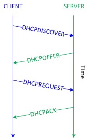
Figure 2-1: DHCP operation
Network address translation (NAT) virtualizes IP addresses by mapping private, non-routable IP addresses (discussed in Section 2.2.1) that are assigned to internal network devices to public IP addresses when communication across the internet is required. NAT is commonly implemented on firewalls and routers to conserve public IP addresses.
Key Terms:
- A media access control (MAC) address is a unique 48-bit or 64-bit identifier assigned to a network interface controller (NIC) for communications at the Data Link layer of the OSI model (discussed in Section 2.3.1).
- The Dynamic Host Configuration Protocol (DHCP) is a network management protocol that dynamically assigns (leases) IP addresses and other network configuration parameters (such as default gateway and Domain Name System [DNS] information) to devices on a network.
- A default gateway is a network device, such as a router or switch, to which an endpoint sends network traffic when a specific destination IP address is not specified by an application or service, or when the endpoint does not know how to reach a specified destination.
- The Domain Name System (DNS) is a decentralized, hierarchical directory service that maps IP addresses to domain names for computers, servers, and other resources on a network and the internet. DNS is analogous to a phone book for the internet.
- An octet is a group of 8 bits in a 32-bit IPv4 address.
- A hextet is a group of four 4-bit hexadecimal digits in a 128-bit IPv6 address.
- The Address Resolution Protocol (ARP) translates a logical address, such as an IP address, to a physical MAC address. The Reverse Address Resolution Protocol (RARP) translates a physical MAC address to a logical address.
- Network address translation (NAT) virtualizes IP addresses by mapping private, non-routable IP addresses assigned to internal network devices to public IP addresses.
IP addressing basics
Data packets are routed over a Transmission Control Protocol/Internet Protocol (TCP/IP) network using IP addressing information. IPv4, which is the most widely deployed version of IP, consists of a 32-bit logical IP address. The first four bits in an octet are known as the high-order bits (the first bit in the octet is referred to as the most significant bit); the last four bits in an octet are known as the low-order bits (the last bit in the octet is referred to as the least significant bit).
Each bit position represents its value (see Table 2-2) if the bit is "on" (1); otherwise, the bit's value is zero ("off" or 0).
Key Terms:
- The first four bits in a 32-bit IPv4 address octet are referred to as the high-order bits.
- The last four bits in a 32-bit IPv4 address octet are referred to as the low-order bits.
- The first bit in a 32-bit IPv4 address octet is referred to as the most significant bit.
- The last bit in a 32-bit IPv4 address octet is referred to as the least significant bit.
Table 2-2: Bit Position Values in an IPv4 Address
| High-order bits | Low-order bits | ||||||
| 128 | 64 | 32 | 16 | 8 | 4 | 2 | 1 |
Each octet contains an 8-bit number with a value of 0 to 255. Table 2-3 shows a partial list of octet values in binary notation.
Table 2-3: Binary Notation of Octet Values
| Decimal | Binary | Decimal | Binary | Decimal | Binary | Decimal | Binary |
| 255 | 1111 1111 | 200 | 1100 1000 | 128 | 1000 0000 | 8 | 0000 1000 |
| 254 | 1111 1110 | 192 | 1100 0000 | 120 | 0111 1000 | 7 | 0000 0111 |
| 253 | 1111 1101 | 180 | 1011 0100 | 110 | 0110 1110 | 6 | 0000 0110 |
| 252 | 1111 1100 | 172 | 1010 1100 | 100 | 0110 0100 | 5 | 0000 0101 |
| 251 | 1111 1011 | 170 | 1010 1010 | 96 | 0110 0000 | 4 | 0000 0100 |
| 250 | 1111 1010 | 160 | 1010 0000 | 90 | 0101 1010 | 3 | 0000 0011 |
| 249 | 1111 1001 | 150 | 1001 0110 | 64 | 0100 0000 | 2 | 0000 0010 |
| 248 | 1111 1000 | 140 | 1000 1100 | 32 | 0010 0000 | 1 | 0000 0001 |
| 224 | 1110 0000 | 130 | 1000 0010 | 16 | 0001 0000 | 0 | 0000 0000 |
The five different IPv4 address classes (indicated by the high-order bits) are shown in Table 2-4.
Table 2-4: IP Address Classes
| Class | Purpose | High-Order Bits | Address Range | Max. # of Hosts |
| A | Large networks | 0 | 1 to 126 | 16,777,214 |
| B | Medium-size networks | 10 | 128 to 191 | 65,534 |
| C | Small networks | 110 | 192 to 223 | 254 |
| D | Multicast | 1110 | 224 to 239 | ─ |
| E | Experimental | 1111 | 240 to 254 | ─ |
The address range 127.0.0.1 to 127.255.255.255 is a loopback network used for testing and troubleshooting. Packets sent to a loopback (or localhost) address – such as 127.0.0.1 – are immediately routed back to the source device.
A subnet mask is a number that hides the network portion of an IPv4 address, leaving only the host portion of the IP address. The network portion of a subnet mask is represented by contiguous "on" (1) bits beginning with the most significant bit. For example, in the subnet mask 255.255.255.0, the first three octets represent the network portion and the last octet represents the host portion of an IP address. Recall that the decimal number 255 is represented in binary notation as 1111 1111 (refer back to Table 2-2).
Key Terms:
- A subnet mask is a number that hides the network portion of an IPv4 address, leaving only the host portion of the IP address.
The default (or standard) subnet masks for Class A, B, and C networks are:
- Class A: 255.0.0.0
- Class B: 255.255.0.0
- Class C: 255.255.255.0
Several IPv4 address ranges are reserved for use in private networks and are not routable on the internet, including:
- 10.0.0.0–10.255.255.255 (Class A)
- 172.16.0.0–172.31.255.255 (Class B)
- 192.168.0.0–192.168.255.255 (Class C)
The 32-bit address space of an IPv4 address limits the total number of unique public IP addresses to about 4.3 billion. The widespread use of NAT (discussed in Section 2.2) delayed the inevitable depletion of IPv4 addresses but, as of 2018, the pool of available IPv4 addresses that can be assigned to organizations has officially been depleted (a small pool of IPv4 addresses has been reserved by each regional internet registry to facilitate the transition to IPv6). IPv6 addresses, which use a 128-bit hexadecimal address space providing about 3.4 x 1038 (340 hundred undecillion) unique IP addresses, was created to replace IPv4 when the IPv4 address space was exhausted.
IPv6 addresses consist of 32 hexadecimal numbers grouped into eight hextets of four hexadecimal digits, separated by a colon. A hexadecimal digit is represented by 4 bits (refer to Table 2-1), so each hextet is 16 bits (four 4-bit hexadecimal digits) and eight 16-bit hextets equals 128 bits.
An IPv6 address is further divided into two 64-bit segments: The first (also referred to as the "top" or "upper") 64 bits represent the network part of the address, and the last (also referred to as the "bottom" or "lower") 64 bits represent the node or interface part of the address. The network part is further subdivided into a 48-bit global network address and a 16-bit subnet. The node or interface part of the address is based on the MAC address (discussed in Section 2.2) of the node or interface.
The basic format for an IPv6 address is: xxxx:xxxx:xxxx:xxxx:xxxx:xxxx:xxxx:xxxx where x represents a hexadecimal digit (0–f).
This is an example of an IPv6 address: 2001:0db8:0000:0000:0008:0800:200c:417a
The IETF has defined several rules to simplify an IPv6 address:
- Leading zeroes in an individual hextet can be omitted, but each hextet must have at least one hexadecimal digit, except as noted in the next rule. Applying this rule to the previous example yields this result: 2001:db8:0:0:8:800:200c:417a.
- Two colons (::) can be used to represent one or more groups of 16 bits of zeros, and leading or trailing zeroes in an address; the :: can appear only once in an IPv6 address. Applying this rule to the previous example yields this result: 2001:db8::8:800:200c:417a.
- In mixed IPv4 and IPv6 environments, the form x:x:x:x:x;x:d.d.d.d can be used, in which x represents the six high-order 16-bit hextets of the address and d represents the four low-order 8-bit octets (in standard IPv4 notation) of the address. For example, 0db8:0:0:0:0:FFFF:129.144.52.38 is a valid IPv6 address. Application of the previous two rules to this example yields this result: db8::ffff:129.144.52.38.
IPv6 security features are specified in Request For Comments (RFC) 7112 and include techniques to prevent fragmentation exploits in IPv6 headers and implementation of Internet Protocol Security (IPsec, discussed in Section 2.6.4) at the Network layer of the OSI model (discussed in Section 2.3.1).
Introduction to subnetting
Subnetting is a technique used to divide a large network into smaller, multiple subnetworks by segmenting an IP address into two parts: the network and the host. Subnetting can be used to limit network traffic or limit the number of devices that are visible to, or can connect to, each other. Routers examine IP addresses and subnet values (called masks) and determine whether to forward packets between networks. With IP addressing, the subnet mask is a required element.
Key Terms:
- Subnetting is a technique used to divide a large network into smaller, multiple subnetworks.
For a Class C IPv4 address, there are 254 possible node (or host) addresses (28 or 256 potential addresses, but you lose two addresses for each network: one for the base network address and the other for the broadcast address). A typical Class C network uses a default 24-bit subnet mask (255.255.255.0). This subnet mask value identifies the network portion of an IPv4 address with the first three octets being all ones (11111111 in binary notation, 255 in decimal notation). The mask displays the last octet as zero (00000000 in binary notation). For a Class C IPv4 address with the default subnet mask, the last octet is where the node-specific values of the IPv4 address are assigned.
For example, in a network with an IPv4 address of 192.168.1.0 and a mask value of 255.255.255.0, the network portion of the address is 192.168.1 and there are 254 node addresses (192.168.1.1 through 192.168.1.254) available. Remember, the first address (192.168.1.0) is the base network and the last address (192.168.1.255) is the broadcast address.
Class A and Class B IPv4 addresses use smaller mask values and support larger numbers of nodes than Class C IPv4 addresses for their default address assignments. Class A networks use a default 8-bit (255.0.0.0) subnet mask, which provides a total of more than 16 million (256 x 256 x 256) available IPv4 node addresses. Class B networks use a default 16-bit (255.255.0.0) subnet mask, which provides a total of 65,534 (256x256, minus the network address and the broadcast address) available IPv4 node addresses.
Unlike subnetting, which divides an IPv4 address along an arbitrary (default) classful 8-bit boundary (8 bits for a Class A network, 16 bits for a Class B network, 24 bits for a Class C network), classless inter-domain routing (CIDR) allocates address space on any address bit boundary (known as variable-length subnet masking, or VLSM). For example, using CIDR, a Class A network could be assigned a 24-bit mask (255.255.255.0, instead of the default 8-bit 255.0.0.0 mask) to limit the subnet to only 254 addresses, or a 23-bit mask (255.255.254.0) to limit the subnet to 512 addresses.
CIDR is used to reduce the size of routing tables on internet routers by aggregating multiple contiguous network prefixes (known as supernetting) and also helped to slow the depletion of public IPv4 addresses (discussed in Section 2.2.1).
Key Terms:
- classless inter-domain routing (CIDR) is a method for allocating IP addresses and IP routing that replaces classful IP addressing (for example, Class A, B, and C networks) with classless IP addressing.
- Variable-length subnet masking (VLSM) is a technique that enables IP address spaces to be divided into different sizes.
- Supernetting aggregates multiple contiguous smaller networks into a larger network to enable more efficient Internet routing.
An IP address can be represented with its subnet mask value, using "netbit" or CIDR notation. A netbit value represents the number of ones in the subnet mask and is displayed after an IP address, separated by a forward slash. For example, 192.168.1.0/24 represents a subnet mask consisting of 24 ones:
11111111.11111111.11111111.00000000 (in binary notation) or
255.255.255.0 (in decimal notation)
Packet Encapsulation and Lifecycle
In a circuit-switched network, a dedicated physical circuit path is established, maintained, and terminated between the sender and receiver across a network for each communications session. Prior to the development of the internet, most communications networks, such as telephone company networks, were circuit-switched. As discussed in Section 2.1.1, the internet is a packet-switched network comprising hundreds of millions of routers and billions of servers and user endpoints. In a packet-switched network, devices share bandwidth on communications links to transport packets between a sender and receiver across a network. This type of network is more resilient to error and congestion than circuit-switched networks.
Key Terms:
- In a circuit-switched network, a dedicated physical circuit path is established, maintained, and terminated between the sender and receiver across a network for each communications session.
- In a packet-switched network, devices share bandwidth on communications links to transport packets between a sender and receiver across a network.
An application that needs to send data across the network, for example, from a server to a client computer first creates a block of data and sends it to the TCP stack on the server. The TCP stack places the block of data into an output buffer on the server and determines the Maximum Segment Size (MSS) of individual TCP blocks (segments) permitted by the server operating system. The TCP stack then divides the data blocks into appropriately sized segments (for example, 1460 bytes), adds a TCP header, and sends the segment to the IP stack on the server.
The IP stack adds source (sender) and destination (receiver) IP addresses to the TCP segment (which is now called an IP packet) and notifies the server operating system that it has an outgoing message that is ready to be sent across the network. When the server operating system is ready, the IP packet is sent to the network interface card (NIC), which converts the IP packet to bits and sends the message across the network.
On their way to the destination computer, the packets typically traverse several network and security devices such as switches, routers, and firewalls before reaching the destination computer, where the encapsulation process described is reversed.
The OSI and TCP/IP models
The Open Systems Interconnection (OSI) and Transmission Control Protocol/Internet Protocol (TCP/IP) models define standard protocols for network communication and interoperability. Using a layered approach, the OSI and TCP/IP models:
- Clarify the general functions of communications processes
- Reduce complex networking processes into simpler sublayers and components
- Promote interoperability through standard interfaces
- Enable vendors to change individual features at a single layer rather than rebuilding the entire protocol stack
- Facilitate logical troubleshooting
Defined by the International Organization for Standardization (ISO – not an acronym, but the adopted organizational name from the Greek language, meaning "equal"), the OSI model consists of seven layers:
- Application (Layer 7 or L7). This layer identifies and establishes availability of communication partners, determines resource availability, and synchronizes communication. Protocols that function at the Application layer include:
- File Transfer Protocol (FTP). Used to copy files from one system to another on TCP ports 20 (the data port) and 21 (the control port)
- Hypertext Transfer Protocol (HTTP). Used for communication between web servers and web browsers on TCP port 80
- Hypertext Transfer Protocol Secure (HTTPS). Used for Secure Sockets Layer/Transport Layer Security (SSL/TLS) encrypted communications between web servers and web browsers on TCP port 443 (and other ports, such as 8443)
- Internet Message Access Protocol (IMAP). A store-and-forward electronic mail protocol that allows an email client to access, manage, and synchronize email on a remote mail server on TCP and UDP port 143
- Post Office Protocol Version 3 (POP3). An email retrieval protocol that allows an email client to access email on a remote mail server on TCP port 110
- Simple Mail Transfer Protocol (SMTP). Used to send and receive email across the internet on TCP/UDP port 25
- Simple Network Management Protocol (SNMP). Used to collect network information by polling stations and sending traps (or alerts) to a management station on TCP/UDP ports 161 (agent) and 162 (manager)
- Telnet. Provides terminal emulation for remote access to system resources on TCP/UDP port 23
- Presentation (Layer 6 or L6). This layer provides coding and conversion functions (such as data representation, character conversion, data compression, and data encryption) to ensure that data sent from the Application layer of one system is compatible with the Application layer of the receiving system. Protocols that function at the Presentation layer include:
- American Standard Code for Information Interchange (ASCII). A character-encoding scheme based on the English alphabet, consisting of 128 characters
- Extended Binary-Coded Decimal Interchange Code (EBCDIC). An 8-bit characterencoding scheme largely used on mainframe and mid-range computers
- Graphics Interchange Format (GIF). A bitmap image format that allows up to 256 colors and is suitable for images or logos (but not photographs)
- Joint Photographic Experts Group (JPEG). A photographic compression method used to store and transmit photographs
- Motion Picture Experts Group (MPEG). An audio and video compression method used to store and transmit audio and video files
- Session (Layer 5 or L5). This layer manages communication sessions (service requests and service responses) between networked systems, including connection establishment, data transfer, and connection release. Protocols that function at the Session layer include:
- Network File System (NFS). Facilitates transparent user access to remote resources on a UNIX-based TCP/IP network
- remote procedure call (RPC). A client-server network redirection protocol
- Secure Shell (SSH). Establishes an encrypted tunnel between a client and server
- Session Initiation Protocol (SIP). An open signaling protocol standard for establishing, managing and terminating real-time communications — such as voice, video, and text — over large IP-based networks
- Transport (Layer 4 or L4). This layer provides transparent, reliable data transport and end-to-end transmission control. Specific Transport layer functions include:
- Flow control (managing data transmission between devices by ensuring that the transmitting device doesn't send more data than the receiving device can process)
- Multiplexing (enabling data from multiple applications to be simultaneously transmitted over a single physical link)
- Virtual circuit management (establishing, maintaining, and terminating virtual circuits)
- Error checking and recovery (detecting transmission errors and taking action to resolve any errors that occur, such as requesting that data be retransmitted) TCP and UDP port numbers assigned to applications and services are defined at the Transport layer. Protocols that function at the Transport layer include:
- Transmission Control Protocol (TCP). A connection-oriented (a direct connection between network devices is established before data segments are transferred) protocol that provides reliable delivery (received segments are acknowledged and retransmission of missing or corrupted segments is requested) of data. TCP connections are established via a three-way handshake. The additional overhead associated with connection establishment, acknowledgment, and error correction means that TCP is generally slower than connectionless protocols such as User Datagram Protocol (UDP).
- User Datagram Protocol (UDP). A connectionless (a direct connection between network devices is not established before datagrams are transferred) protocol that provides best-effort delivery (received datagrams are not acknowledged and missing or corrupted datagrams are not requested) of data. UDP has no overhead associated with connection establishment, acknowledgment, sequencing, or error-checking and recovery. UDP is ideal for data that requires fast delivery, as long as that data isn't sensitive to packet loss and doesn't need to be fragmented. Applications that use UDP include Domain Name System (DNS), Simple Network Management Protocol (SNMP), and streaming audio or video.
- Stream Control Transmission Protocol (SCTP). A message-oriented protocol (similar to UDP) that ensures reliable, in-sequence transport with congestion control (similar to TCP)
- Network (Layer 3 or L3). This layer provides routing and related functions that enable data to be transported between systems on the same network or on interconnected networks. Routing protocols (discussed in Section 2.1.3) are defined at this layer. Logical addressing of devices on the network is accomplished at this layer using routed protocols such as the Internet Protocol (IP). Routers operate at the Network layer of the OSI model.
- Data Link (Layer 2). This layer ensures that messages are delivered to the proper device across a physical network link. This layer also defines the networking protocol (for example, Ethernet) used to send and receive data between individual devices and formats messages from layers above into frames for transmission, handles point-topoint synchronization and error control, and can perform link encryption. Switches typically operate at Layer 2 of the OSI model (although multilayer switches that operate at different layers also exist). The Data Link layer is further divided into two sublayers:
- Logical Link Control (LLC). The LLC sublayer provides an interface for the MAC sublayer; manages the control, sequencing, and acknowledgment of frames being passed up to the Network layer or down to the Physical layer; and manages timing and flow control.
- Media access control (MAC). The MAC sublayer is responsible for framing and performs error control using a cyclic redundancy check (CRC), identifies MAC addresses (discussed in Section 2.2), and controls media access.
- Physical (Layer 1 or L1). This layer sends and receives bits across the network medium (cabling or wireless links) from one device to another. It specifies the electrical, mechanical, and functional requirements of the network, including network topology, cabling and connectors, and interface types, and the process for converting bits to electrical (or light) signals that can be transmitted across the physical medium.
Key Terms:
- A TCP segment is a protocol data unit (PDU) defined at the Transport layer of the OSI model.
- A protocol data unit (PDU) is a self-contained unit of data (consisting of user data or control information and network addressing).
- In TCP, a three-way handshake is used to establish a connection. For example, a PC initiates a connection with a server by sending a TCP SYN (Synchronize) packet. The server replies with a SYN ACK packet (Synchronize Acknowledgment). Finally, the PC sends an ACK or SYN-ACK-ACK packet, acknowledging the server's acknowledgment, and data communication commences.
- A UDP datagram is a PDU defined at the Transport layer of the OSI model.
- Flow control monitors the flow of data between devices to ensure that a receiving device, which may not necessarily be operating at the same speed as the transmitting device, doesn't drop packets.
- A cyclic redundancy check (CRC) is a checksum used to create a message profile. The CRC is recalculated by the receiving device. If the recalculated CRC doesn't match the received CRC, the packet is dropped and a request to resend the packet is transmitted back to the device that sent the packet.
The TCP/IP model was originally developed by the U.S. Department of Defense (DoD) and actually preceded the OSI model. Whereas the OSI model is a theoretical model used to logically describe networking processes, the TCP/IP model defines actual networking requirements, for example, for frame construction. The TCP/IP model consists of four layers (see Figure 2-2):
- Application (Layer 4 or L4). This layer consists of network applications and processes, and it loosely corresponds to Layers 5 through 7 of the OSI model.
- Transport (Layer 3 or L3). This layer provides end-to-end delivery and it corresponds to Layer 4 of the OSI model.
- Internet (Layer 2 or L2). This layer defines the IP datagram and routing, and it corresponds to Layer 3 of the OSI model.
- Network Access (Layer 1 or L1). Also referred to as the Link layer, this layer contains routines for accessing physical networks and it corresponds to Layers 1 and 2 of the OSI model.
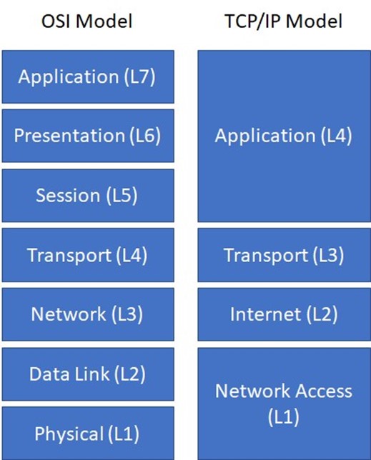
Figure 2-2: The OSI model and the TCP/IP model
Data encapsulation
In the OSI and TCP/IP models, data is passed from the highest layer (L7 in the OSI model, L4 in the TCP/IP model) downward through each layer to the lowest layer (L1 in the OSI model and TCP/IP model), and is then transmitted across the network medium to the destination node, where it is passed upward from the lowest layer to the highest layer. Each layer communicates only with the adjacent layer immediately above and below it. This communication is achieved through a process known as data encapsulation (or data hiding), which wraps protocol information from the layer immediately above in the data section of the layer immediately below.
Key Terms:
- Data encapsulation (or data hiding) wraps protocol information from the (OSI or TCP/IP) layer immediately above in the data section of the layer below.
A protocol data unit (PDU) describes a unit of data at a particular layer of a protocol. For example, in the OSI model, a Layer 1 PDU is known as a bit, a Layer 2 PDU is known as a frame, a Layer 3 PDU is known as a packet, and a Layer 4 PDU is known as a segment or datagram. When a client or server application sends data across a network, a header (and trailer in the case of Layer 2 frames) is added to each data packet from the adjacent layer below it as it passes through the protocol stack. On the receiving end, the headers (and trailers) are removed from each data packet as it passes through the protocol stack to the receiving application.
Network Security Models
This section describes perimeter-based and Zero Trust network security models.
Perimeter-based network security strategy
Perimeter-based network security models date back to the early mainframe era (circa late 1950s), when large mainframe computers were located in physically secure "machine rooms" that could be accessed by only a relatively limited number of remote job entry (RJE) "dumb" terminals that were directly connected to the mainframe and also located in physically secure areas. Today's data centers are the modern equivalent of machine rooms, but perimeter-based physical security is no longer sufficient for several obvious, but important reasons:
- Mainframe computers predate the internet. In fact, mainframe computers predate ARPANET, which predates the internet. Today, an attacker uses the internet to remotely gain access, rather than to physically breach the data center perimeter.
- Data centers today are remotely accessed by millions of remote endpoint devices from anywhere and at any time. Unlike the RJEs of the mainframe era, modern endpoints (including mobile devices) are far more powerful than many of the early mainframe computers and are targets themselves.
- The primary value of the mainframe computer was its processing power. The relatively limited data that was produced was typically stored on near-line media, such as tape. Today, data is the target, it is stored online in data centers and in the cloud, and it is a high value target for any attacker.
The primary issue with a perimeter-based network security strategy in which countermeasures are deployed at a handful of well-defined ingress and egress points to the network is that it relies on the assumption that everything on the internal network can be trusted. However, this assumption is no longer safe to make, given modern business conditions and computing environments where:
- Remote employees, mobile users, and cloud computing solutions blur the distinction between "internal" and "external."
- Wireless technologies, the proliferation of partner connections, and the need to support guest users introduce countless additional pathways into the network branch offices that may be located in untrusted countries or regions.
- Insiders, whether intentionally malicious or just careless, may present a very real security threat.
Perimeter-based approach strategies fail to account for:
- The potential for sophisticated cyberthreats to penetrate perimeter defenses, in which case they would then have free passage on the internal network
- Scenarios where malicious users can gain access to the internal network and sensitive resources by using the stolen credentials of trusted users
- The reality that internal networks are rarely homogeneous, but instead include pockets of users and resources with inherently different levels of trust/sensitivity that should ideally be separated in any event (for example, research and development and financial systems versus print/file servers)
A broken trust model is not the only issue with perimeter-centric approaches to network security. Another contributing factor is that traditional security devices and technologies (such as port-based firewalls) commonly used to build network perimeters let too much unwanted traffic through. Typical shortcomings in this regard include the inability to:
- Definitively distinguish good applications from bad ones (which leads to overly permissive access control settings)
- Adequately account for encrypted application traffic
- Accurately identify and control users (regardless of where they're located or which devices they're using)
- Filter allowed traffic not only for known application-borne threats but also for unknown ones
The net result is that re-architecting defenses in a way that creates pervasive internal trust boundaries is, by itself, insufficient. You must also ensure that the devices and technologies used to implement these boundaries actually provide the visibility, control, and threat inspection capabilities needed to securely enable essential business applications while still thwarting modern malware, targeted attacks, and the unauthorized exfiltration of sensitive data.
Zero Trust security
Introduced by Forrester Research, the Zero Trust security model addresses some of the limitations of perimeter-based network security strategies by removing the assumption of trust from the equation. With Zero Trust, essential security capabilities are deployed in a way that provides policy enforcement and protection for all users, devices, applications, data resources, and the communications traffic between them, regardless of location.
In particular, with Zero Trust there is no default trust for any entity — including users, devices, applications, and packets — regardless of what it is and its location on or relative to the enterprise network. Verification that authorized entities are always doing only what they're allowed to do also is no longer optional in a Zero Trust model; it's now mandatory.
The implications for these two changes are, respectively:
- The need to establish trust boundaries that effectively compartmentalize different segments of the internal computing environment. The general idea is to move security functionality closer to the different pockets of resources that require protection. This way security can always be enforced regardless of the point of origin of associated communications traffic.
- The need for trust boundaries to do more than just initial authorization and access control enforcement. To "always verify" also requires ongoing monitoring and inspection of associated communications traffic for subversive activities (such as threats).
Benefits of implementing a Zero Trust network include:
- Clearly improved effectiveness in mitigating data loss with visibility and safe enablement of applications, and detection and prevention of cyberthreats
- Greater efficiency for achieving and maintaining compliance with security and privacy mandates, using trust boundaries to segment sensitive applications, systems, and data
- Improved ability to securely enable transformative IT initiatives, such as user mobility, BYOD/BYOA, infrastructure virtualization, and cloud computing
- Lower total cost of ownership (TCO) with a consolidated and fully integrated security operating platform, rather than a disparate array of siloed, purpose-built security point products
Core Zero Trust design principles
The core Zero Trust principles that define the operational objectives of a Zero Trust implementation include:
- Ensure that all resources are accessed securely, regardless of location. This principle suggests not only the need for multiple trust boundaries but also increased use of secure access for communication to or from resources, even when sessions are confined to the "internal" network. It also means ensuring that the only devices allowed access to the network have the correct status and settings, have an approved VPN client and proper passcodes, and are not running malware.
- Adopt a least privilege strategy and strictly enforce access control. The goal is to minimize allowed access to resources as a means to reduce the pathways available for malware and attackers to gain unauthorized access — and subsequently to spread laterally and/or infiltrate sensitive data.
- Inspect and log all traffic. This principle reiterates the need to "always verify" while also reinforcing that adequate protection requires more than just strict enforcement of access control. Close and continuous attention must also be given to exactly what "allowed" applications are actually doing, and the only way to accomplish these goals is to inspect the content for threats.
Key Terms:
- The principle of least privilege in network security requires that only the permission or access rights necessary to perform an authorized task are granted.
Zero Trust conceptual architecture
The main components of a Zero Trust conceptual architecture (shown in Figure 2-3) include:
- Zero Trust Segmentation Platform. The Zero Trust Segmentation Platform is referred to as a network segmentation gateway by Forrester Research. It is the component used to define internal trust boundaries. That is, it provides the majority of the security functionality needed to deliver on the Zero Trust operational objectives, including the ability to:
 Enable secure network access
 - Granularly control traffic flow to and from resources
- Continuously monitor allowed sessions for any threat activity
Although Figure 2-3 depicts the Zero Trust Segmentation Platform as a single component in a single physical location, in practice – because of performance, scalability, and physical limitations – an effective implementation is more likely to entail multiple instances distributed throughout an organization's network. The solution also is designated as a "platform" to reflect that it is an aggregation of multiple distinct (and potentially distributed) security technologies that operate as part of a holistic threat protection framework to reduce the attack surface and correlate information about threats that are found.
- Trust zones. Forrester Research refers to a trust zone as a micro core and perimeter (MCAP). A trust zone is a distinct pocket of infrastructure where the member resources not only operate at the same trust level but also share similar functionality.
Functionality such as protocols and types of transactions must be shared because it is needed to actually minimize the number of allowed pathways into and out of a given zone and, in turn, minimize the potential for malicious insiders and other types of threats to gain unauthorized access to sensitive resources.
Examples of trust zones shown in Figure 2-3 include the user (or campus) zone, a wireless zone for guest access, a cardholder data zone, database and application zones for multi-tier services, and a zone for public-facing web applications.
Remember, too, that a trust zone is not intended to be a "pocket of trust" where systems (and therefore threats) within the zone can communicate freely and directly with each other. For a full Zero Trust implementation, the network would be configured to ensure that all communications traffic — including traffic between devices in the same zone — is intermediated by the corresponding Zero Trust Segmentation Platform.
- Management infrastructure. Centralized management capabilities are crucial to enabling efficient administration and ongoing monitoring, particularly for implementations involving multiple distributed Zero Trust Segmentation Platforms. A data acquisition network also provides a convenient way to supplement the native monitoring and analysis capabilities for a Zero Trust Segmentation Platform. Session logs that have been forwarded to a data acquisition network can then be processed by any number of out-of-band analysis tools and technologies intended, for example, to further enhance network visibility, detect unknown threats, or support compliance reporting.

Figure 2-3: Zero Trust conceptual architecture
Key Zero Trust criteria and capabilities
The core of any Zero Trust network security architecture is the Zero Trust Segmentation Platform, so you must choose the correct solution. Key criteria and capabilities to consider when selecting a Zero Trust Segmentation Platform, include:
- Secure access. Consistent secure IPsec and SSL VPN connectivity is provided for all employees, partners, customers, and guests wherever they're located (for example, at remote or branch offices, on the local network, or over the internet). Policies to determine which users and devices can access sensitive applications and data can be defined based on application, user, content, device, and device state.
- Inspection of all traffic. Application identification accurately identifies and classifies all traffic, regardless of ports and protocols, and evasive tactics such as port hopping or encryption. Application identification eliminates methods that malware may use to hide from detection and provides complete context into applications, associated content, and threats.
- Least privileges access control. The combination of application, user, and content identification delivers a positive control model that allows organizations to control interactions with resources based on an extensive range of business-relevant attributes, including the specific application and individual functions being used, user and group identity, and the specific types or pieces of data being accessed (such as credit card or Social Security numbers). The result is truly granular access control that safely enables the correct applications for the correct sets of users while automatically preventing unwanted, unauthorized, and potentially harmful traffic from gaining access to the network.
- Cyberthreat protection. A combination of anti-malware, intrusion prevention, and cyberthreat prevention technologies provides comprehensive protection against both known and unknown threats, including threats on mobile devices. Support for a closedloop, highly integrated defense also ensures that inline enforcement devices and other components in the threat protection framework are automatically updated.
- Coverage for all security domains. Virtual and hardware appliances establish consistent and cost-effective trust boundaries throughout an organization's entire network, including in remote or branch offices, for mobile users, at the internet perimeter, in the cloud, at ingress points throughout the data center, and for individual areas wherever they might exist.
Implementing a Zero Trust design
Implementation of a Zero Trust network security model doesn't require a major overhaul of an organization's network and security infrastructure. A Zero Trust design architecture can be implemented in a way that requires only incremental modifications to the existing network and is completely transparent to your users. Advantages of such a flexible, non-disruptive deployment approach include minimizing the potential impact on operations and being able to spread the required investment and work effort over time.
To get started, you can configure a Zero Trust Segmentation Platform in listen-only mode to obtain a detailed picture of traffic flows throughout the network, including where, when, and the extent to which specific users are using specific applications and data resources.
Once you have a detailed understanding of the network traffic flows in the environment, the next step is to define trust zones and incrementally establish corresponding trust boundaries based on relative risk and/or sensitivity of the data involved:
- Deploy devices in appropriate locations to establish internal trust boundaries for defined trust zones
- Configure the appropriate enforcement and inspection policies to effectively put each trust boundary "online"
Next, you can then progressively establish trust zones and boundaries for other segments of the computing environment based on their relative degree of risk. Examples where secure trust zones can be established are:
- IT management systems and networks (where a successful breach could lead to compromise of the entire network)
- Partner resources and connections (business-to-business, or B2B)
- High-profile, customer-facing resources and connections (business-to-consumer, or B2C)
- Branch offices in risky countries or regions, followed by all other branch offices
- Guest access networks (both wireless and wired)
- Campus networks
Zero Trust principles and concepts need to be implemented at major access points to the internet. You will have to replace or augment legacy network security devices with a Zero Trust Segmentation Platform at this deployment stage to gain all of the requisite capabilities and benefits of a Zero Trust security model.
Cloud and Data Center Security
Data centers are rapidly evolving from a traditional, closed environment with static, hardwarebased computing resources to one in which traditional and cloud computing technologies are mixed (see Figure 2-4).
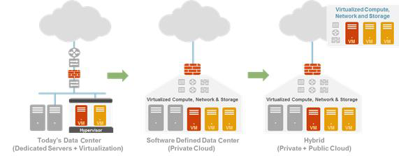
Figure 2-4: Data centers are evolving to include a mix of hardware and cloud computing technologies.
The benefit of moving toward a cloud computing model – private, public, or hybrid – is that it improves operational efficiencies and lowers capital expenditures:
- Optimizes existing hardware resources. Instead of using a "one server, one application" model, you can run multiple virtual applications on a single physical server, which means that organizations can leverage their existing hardware infrastructure by running more applications within the same system, provided there are sufficient compute and memory resources on the system.
- Reduces data center costs. Reduction of the server hardware "box" count not only reduces the physical infrastructure real estate but also reduces data center costs for power, cooling, and rack space, among others.
- Increases operational flexibility. Through the dynamic nature of virtual machine (VM) provisioning, applications can be delivered more quickly than they can through the traditional method of purchasing them, "racking/stacking," cabling, and so on. This operational flexibility helps improve the agility of the IT organization.
- Maximizes efficiency of data center resources. Because applications can experience asynchronous or bursty demand loads, virtualization provides a more efficient way to address resource contention issues and maximize server use. It also provides a better way to address server maintenance and backup challenges. For example, IT staff can migrate VMs to other virtualized servers or hypervisors while performing hardware or software upgrades.
Cloud computing depends on virtualization
Cloud computing is not a location, but rather a pool of resources that can be rapidly provisioned in an automated, on-demand manner. The U.S. National Institute of Standards and Technology (NIST) defines cloud computing in Special Publication (SP) 800-145 as "a model for enabling ubiquitous, convenient, on-demand network access to a shared pool of configurable computing resources (such as networks, servers, storage, applications, and services) that can be rapidly provisioned and released with minimal management effort or service provider interaction."
The value of cloud computing is the ability to pool resources to achieve economies of scale and agility. This ability to pool resources is true for private or public clouds. Instead of having many independent and often under-used servers deployed for your enterprise applications, pools of resources are aggregated, consolidated, and designed to be elastic enough to scale with the needs of your organization.
The move toward cloud computing not only brings cost and operational benefits but also technology benefits. Data and applications are easily accessed by users no matter where they reside, projects can scale easily, and consumption can be tracked effectively. Virtualization is a critical part of a cloud computing architecture that, when combined with software orchestration and management tools, allows you to integrate disparate processes so that they can be automated, easily replicated, and offered on an as-needed basis.
Cloud computing security considerations and requirements
With the use of cloud computing technologies, your data center environment can evolve from a fixed environment where applications run on dedicated servers toward an environment that is dynamic and automated, where pools of computing resources are available to support application workloads that can be accessed anywhere, anytime, from any device.
Security remains a significant challenge when you embrace this new dynamic, cloud-computing fabric environment. Many of the principles that make cloud computing attractive are counter to network security best practices:
- Cloud computing doesn't mitigate existing network security risks. The security risks that threaten your network today do not change when you move to the cloud. The shared responsibility model defines who (customer and/or provider) is responsible for what (related to security) in the public cloud. In general terms, the cloud provider is responsible for security "of" the cloud, including the physical security of the cloud data centers, and foundational networking, storage, compute, and virtualization services. The cloud customer is responsible for security "in" the cloud, which is further delineated by the cloud service model. For example, in an infrastructure-as-a-service (IaaS) model, the cloud customer is responsible for the security of the operating systems, middleware, run time, applications, and data. In a platform-as-a-service (PaaS) model, the cloud customer is responsible for the security of the applications and data and the cloud provider is responsible for the security of the operating systems, middleware, and run time. In a SaaS model, the cloud customer is responsible only for the security of the data and the cloud provider is responsible for the full stack from the physical security of the cloud data centers to the application.
- Security requires isolation and segmentation; the cloud relies on shared resources. Security best practices dictate that mission-critical applications and data be isolated in secure segments on the network using the Zero Trust (discussed in Section 2.4.2) principle of "never trust, always verify." On a physical network, Zero Trust is relatively straightforward to accomplish using firewalls and policies based on application and user identity. In a cloud computing environment, direct communication between VMs within a server and in the data center (east-west traffic, discussed in Section 2.5.4) occurs constantly, in some cases across varied levels of trust, making segmentation a difficult task. Mixed levels of trust, when combined with a lack of intra-host traffic visibility by virtualized port-based security offerings, may weaken an organization's security posture.
- Security deployments are process-oriented; cloud computing environments are dynamic. The creation or modification of your cloud workloads can often be done in minutes, yet the security configuration for this workload may take hours, days, or weeks. Security delays are not purposeful; they're the result of a process that is designed to maintain a strong security posture. Policy changes need to be approved, the appropriate firewalls need to be identified, and the relevant policy updates need to be determined. In contrast, the cloud is a highly dynamic environment, with workloads (and IP addresses) constantly being added, removed, and changed. The result is a disconnect between security policy and cloud workload deployments that leads to a weakened security posture. Security technologies and processes must leverage capabilities such as cloning and scripted deployments to automatically scale and take advantage of the elasticity of the cloud while maintaining a strong security posture.
- Multi-tenancy is a key characteristic of the public cloud – and a key risk. Although public cloud providers strive to ensure isolation between their various customers, the infrastructure and resources in the public cloud are shared. Inherent risks in a shared environment include misconfigurations, inadequate or ineffective processes and controls, and the "noisy neighbor" problem (excessive network traffic, disk I/O, or processor utilization can negatively impact other customers sharing the same resource). In hybrid and multi-cloud environments that connect numerous public and/or private clouds, the lines become still more blurred, complexity increases, and security risks become more challenging to address.
As organizations transition from a traditional data center architecture to a public, private, or hybrid cloud environment, enterprise security strategies must be adapted to support changing requirements in the cloud. Key requirements for securing the cloud include:
- Consistent security in physical and virtualized form factors. The same levels of application control and threat prevention should be used to protect both your cloud computing environment and your physical network. First, you need to be able to confirm the identity of your applications, validating their identity and forcing them to use only their standard ports. You also need to be able to block the use of rogue applications while simultaneously looking for and blocking misconfigured applications. Finally, application-specific threat prevention policies should be applied to block both known and unknown malware from moving into and across your network and cloud environment.
- Segment your business applications using Zero Trust principles. To fully maximize the use of computing resources, a relatively common current practice is to mix application workload trust levels on the same compute resource. Although they are efficient in practice, mixed levels of trust introduce new security risks in the event of a compromise. Your cloud security solution needs to be able to implement security policies based on the concept of Zero Trust (discussed in Section 2.4.2) as a means of controlling traffic between workloads while preventing lateral movement of threats.
- Centrally manage security deployments; streamline policy updates. Physical network security is still deployed in almost every organization, so it's critical to have the ability to manage both hardware and virtual form factor deployments from a centralized location using the same management infrastructure and interface. To ensure that security keeps pace with the speed of change that your workflows may exhibit, your security solution should include features that will allow you to lessen, and in some cases eliminate the manual processes that security policy updates often require.
Traditional data security solution weaknesses
Traditional data center security solutions exhibit the same weaknesses found when they are deployed at a perimeter gateway on the physical network – they make their initial positive control network access decisions based on port, using stateful inspection, then they make a series of sequential, negative control decisions using bolted-on feature sets. There are several problems with this approach:
- "Ports first" limits visibility and control. The "ports first" focus of traditional data security solutions limits their ability to see all traffic on all ports, which means that evasive or encrypted applications, and any corresponding threats that may or may not use standard ports can evade detection. For example, many data center applications such as Microsoft Lync, Active Directory, and SharePoint use a wide range of contiguous ports to function properly. You must therefore open all those ports first, exposing those same ports to other applications or cyberthreats.
- They lack any concept of unknown traffic. Unknown traffic is high risk, but represents only a relatively small amount of traffic on every network. Unknown traffic can be a custom application, an unidentified commercial off-the-shelf application, or a threat. The common practice of blocking it all may cripple your business. Allowing it all is highly risky. You need to be able to systematically manage unknown traffic using native policy management tools to reduce your organizational security risks.
- Multiple policies, no policy reconciliation tools. Sequential traffic analysis (stateful inspection, application control, IPS, anti-malware, etc.) in traditional data center security solutions requires a corresponding security policy or profile, often using multiple management tools. The result is that your security policies become convoluted as you build and manage a firewall policy with source, destination, user, port, and action; an application control policy with similar rules; and any other threat prevention rules required. Multiple security policies that mix positive (firewall) and negative (application control, IPS, and anti-malware) control models can cause security holes by missing traffic and/or not identifying the traffic. This situation is made worse when there are no policy reconciliation tools.
- Cumbersome security policy update process. Existing security solutions in the data center do not address the dynamic nature of your cloud environment because your policies have difficulty contending with the numerous dynamic changes that are common in virtual data centers. In a virtual data center, VM application servers often move from one physical host to another, so your security policies must adapt to changing network conditions.
Many cloud security offerings are merely virtualized versions of port and protocol-based security appliances with the same inadequacies as their physical counterparts.
East-west traffic protection
In a virtualized data center (private cloud), there are two different types of traffic, each of which is secured in a different manner (see Figure 2-5):
- North-south refers to data packets that move in and out of the virtualized environment from the host network or a corresponding traditional data center. North-south traffic is secured by one or more physical form factor perimeter edge firewalls. The edge firewall is usually a high-throughput appliance working in high availability active/passive (or active/active) mode to increase resiliency. It controls all the traffic reaching into the data center and authorizes only allowed and "clean" packets to flow into the virtualized environment.
- East-west refers to data packets moving between virtual workloads entirely within the private cloud. East-west traffic is protected by a local, virtualized firewall instantiated on each hypervisor. East-west firewalls are inserted transparently into the application infrastructure and do not necessitate a redesign of the logical topology.
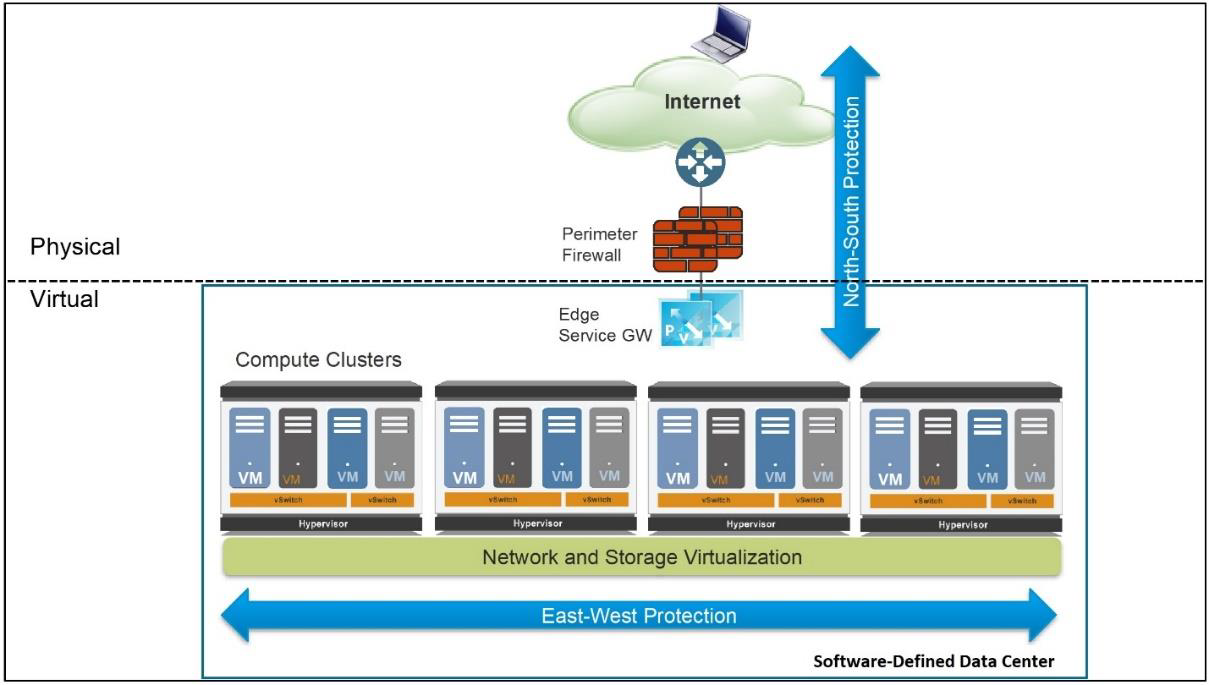
Figure 2-5: Typical virtual data center design architecture
The compute cluster is the building block for hosting the application infrastructure and provides the necessary resources in terms of compute, storage, networking, and security. Compute clusters can be interconnected using OSI Model (discussed in Section 2.3.1) Layer 2 (Data Link) or Layer 3 (Network) technologies such as virtual LAN (VLAN), virtual extensible LAN (VXLAN), or IP, thus providing a domain extension for workload capacity. Innovations in the virtualization space allow VMs to move freely in this private cloud while preserving compute, storage, networking, and security characteristics and postures.
Organizations usually implement security to protect traffic flowing north-south, but this approach is insufficient for protecting east-west traffic within a private cloud. To improve their security posture, enterprises must protect against threats across the entire network, both north-south and east-west.
One common practice in a private cloud is to isolate VMs into different tiers. Isolation provides clear delineation of application functions and allows a security team to easily implement security policies. Isolation is achieved using logical network attributes (such as a VLAN or VXLAN) or logical software constructs (such as security groups). Figure 2-6 displays a simple three-tier application that is composed of a WEB-VM as the front-end, an APP-VM as the application, and a DB-VM providing database services.
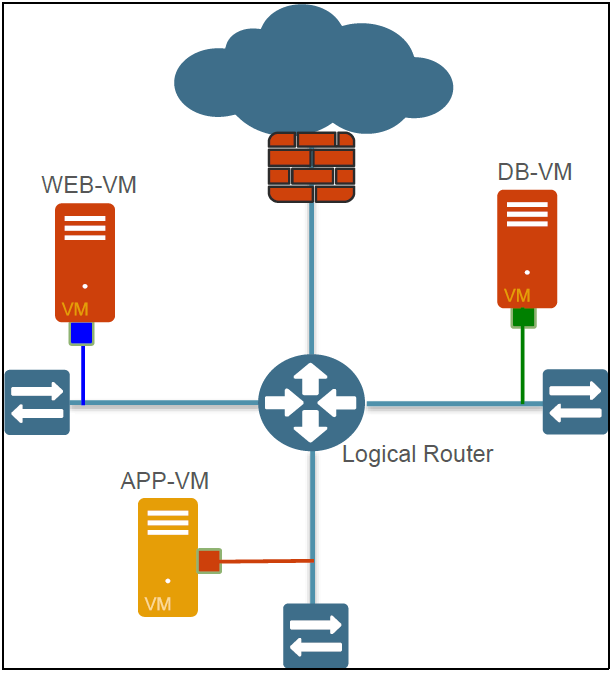
Figure 2-6: Three-tier application hosted in a virtual data center
An attacker has multiple options to steal data from the DB-VM. The first option is to initiate an SQL injection attack by sending HTTP requests containing normalized SQL commands that target an application vulnerability. The second option is to compromise the WEB-VM (using vulnerability exploits), and then move laterally to the APP-VM, initiating a brute-force attack to retrieve the SQL admin password.
Once the DB-VM is compromised, the attacker can hide sensitive data extraction using techniques such as DNS tunneling, or by moving data across the network with NetBIOS, and then off the network via FTP. In fact, attackers using applications commonly found on nearly every network have virtually unlimited options for stealing critical data in this environment. Infiltration into the environment and exfiltration of critical data can be completely transparent and undetected because the data is carried over legitimate protocols (such as HTTP and DNS) that are used for normal business activities.
Virtual data center security best practices dictate a combination of north-south and east-west protection. East-west protection provides the following benefits:
- Authorizes only allowed applications to flow inside the data center, between VMs
- Reduces lateral threat movement when a front-end workload has been compromised (attacker breaches the front-end server using a misconfigured application or unpatched exploit)
- Stops known and unknown threats that are sourced internally within the data center.
- Protects against data theft by leveraging data and file filtering capability and blocking anti-spyware communications to the external world
An added benefit of using virtual firewalls for east-west protection is the unprecedented traffic and threat visibility that the virtualized security device can now provide. Once Traffic logs and Threat logs are turned on, VM-to-VM communications and malicious attacks become visible. This virtual data center awareness allows security teams to optimize policies and enforce cyberthreat protection (for example, IPS, anti-malware, file blocking, data filtering, and DoS protection) where needed.
Implementing security in virtualized data centers
The following approach to security in the evolving data center — from traditional three-tier architectures to virtualized data centers and to the cloud — aligns with practical realities, such as the need to leverage existing best practices and technology investments, and the likelihood that most organizations will transform their data centers incrementally.
This approach consists of four phases:
- Consolidating servers within trust levels. Organizations often consolidate servers within the same trust level into a single virtual computing environment — either one physical host or a cluster of physical hosts. Intra-host communications are generally minimal and inconsequential. As a matter of routine, most traffic is directed "off-box" to users and systems residing at different trust levels. When intra-host communications do happen, the absence of protective safeguards between these virtualized systems is also consistent with the organization's security posture for non-virtualized systems. Live migration features are typically used to enable transfer of VMs only to hosts supporting workloads within the same subnet. Security solutions should incorporate a robust virtual systems capability in which a single instance of the associated countermeasures can be partitioned into multiple logical instances, each with its own policy, management, and event domains. This virtual systems capability enables a single physical device to be used to simultaneously meet the unique requirements of multiple VMs or groups of VMs. Controlling and protecting inter-host traffic with physical network security appliances that are properly positioned and configured is the primary security focus.
- Consolidating servers across trust levels. Workloads with different trust levels often coexist on the same physical host or cluster of physical hosts. Intra-host communications are limited, and live migration features are used to enable transfer of VMs only to hosts that are on the same subnet and that are configured identically with regard to routing of VM-to-VM traffic. Intra-host communication paths are intentionally not configured between VMs with different trust levels. Instead, all traffic is forced "offbox" through a default gateway — such as a physical network security appliance — before it is allowed to proceed to the destination VM. Typically, this off-box routing can be accomplished by configuring separate virtual switches with separate physical network interface cards (NICs) for the VMs at each distinct trust level. As a best practice for virtualization, you should minimize the combination of workloads with different trust levels on the same server. Live migrations of VMs also should be restricted to servers supporting workloads within the same trust levels and within the same subnet. Over time, and in particular, as workloads move to the cloud, maintenance of segmentation based on trust levels becomes more challenging.
- Selective network security virtualization. Intra-host communications and live migrations are architected at this phase. All intra-host communication paths are strictly controlled to ensure that traffic between VMs at different trust levels is intermediated either by an on-box, virtual security appliance or by an off-box, physical security appliance. Long-distance live migrations (for example, between data centers) are enabled by combination of native live migration features with external solutions that address associated networking and performance challenges. The intense processing requirements of solutions such as NGFW virtual appliances will ensure that purposebuilt physical appliances continue to play a key role in the virtualized data center. However, virtual instances are ideally suited for scenarios where countermeasures need to "migrate" along with the workloads they control and protect.
- Dynamic computing fabric. Conventional, static computing environments are transformed into dynamic fabrics (private or hybrid clouds) where underlying resources such as network devices, storage, and servers can be fluidly engaged in whatever combination best meets the needs of the organization at any given point in time. Intrahost communication and live migrations are unrestricted. This phase requires networking and security solutions that not only can be virtualized but are also virtualization-aware and can dynamically adjust as necessary to address communication and protection requirements, respectively. Classification, inspection, and control mechanisms in virtualization-aware security solutions must not be dependent on physical and fixed network-layer attributes. In general, higher-layer attributes such as application, user, and content identification are the basis not only for how countermeasures deliver protection but also for how they dynamically adjust to account for whatever combination of workloads and computing resources exist in their sphere of influence. Associated security management applications also need to be capable of orchestrating the activities of physical and virtual instances of countermeasures first with each other and subsequently with other infrastructure components. This capability is necessary to ensure that adequate protection is optimally delivered in situations where workloads are frequently migrating across data center hosts.
Network Security Technologies
This section describes traditional network security technologies including firewalls, intrusion detection systems and Intrusion Prevention Systems (IDS/IPS), web content filters, virtual private networks (VPNs), data loss prevention (DLP), Unified Threat Management (UTM), and security information and event management (SIEM).
Firewalls
Firewalls have been a cornerstone of network security since the early days of the internet. A firewall is a hardware and/or software platform that controls the flow of traffic between a trusted network (such as a corporate LAN) and an untrusted network (such as the internet)
Packet filtering firewalls
First-generation packet filtering (also known as port-based) firewalls have the following characteristics:
- Operate up to Layer 4 (transport layer) of the OSI model (discussed in Section 2.3.1) and inspect individual packet headers to determine source and destination IP address, protocol (TCP, UDP, ICMP), and port number
- Match source and destination IP address, protocol, and port number information contained within each packet header to a corresponding rule on the firewall that designates whether the packet should be allowed, blocked, or dropped
- Inspect and handle each packet individually, with no information about context or session
Stateful packet inspection (SPI) firewalls
Second-generation stateful packet inspection (also known as dynamic packet filtering) firewalls have the following characteristics:
- Operate up to Layer 4 (transport layer) of the OSI model and maintain state information about the different communication sessions that have been established between hosts on the trusted and untrusted networks
- Inspect individual packet headers to determine source and destination IP address, protocol (TCP, UDP, and ICMP), and port number, during session establishment only, to determine if the session should be allowed, blocked, or dropped based on configured firewall rules
- Once a permitted connection is established between two hosts, the firewall creates and deletes firewall rules for individual connections, as needed, thus effectively creating a tunnel that allows traffic to flow between the two hosts without further inspection of individual packets during the session.
- This type of firewall is very fast, but it is port-based and is highly dependent on the trustworthiness of the two hosts because individual packets aren't inspected after the connection is established.
Application firewalls
Third-generation application (also known as application-layer gateways, proxy-based, and reverse-proxy) firewalls have the following characteristics:
- Operate up to Layer 7 (Application layer) of the OSI model and control access to specific applications and services on the network
- Proxy network traffic rather than permit direct communication between hosts. Requests are sent from the originating host to a proxy server, which analyzes the contents of the
- data packets and, if permitted, sends a copy of the original data packets to the destination host
- Inspect Application layer traffic and thus can identify and block specified content, malware, exploits, websites, and applications or services using hiding techniques such as encryption and non-standard ports. Proxy servers can also be used to implement strong user authentication and web application filtering, and to mask the internal network from untrusted networks. However, proxy servers have a significant negative impact on the overall performance of the network.
Intrusion detection and prevention systems
Intrusion detection systems (IDS) and Intrusion Prevention Systems (IPS) provide real-time monitoring of network traffic and perform deep-packet inspection and analysis of network activity and data. Unlike traditional packet filtering and stateful packet inspection firewalls that examine only packet header information, IDS/IPS examines both the packet header and payload of network traffic. IDS/IPS attempts to match known-bad, or malicious, patterns (or signatures) found within inspected packets. An IDS/IPS is typically deployed to detect and block exploits of software vulnerabilities on target networks.
The primary difference between IDS and IPS is that IDS is considered to be a passive system, whereas IPS is an active system. IDS monitor and analyze network activity and provides alerts to potential attacks and vulnerabilities on the network, but it doesn't perform any preventive action to stop an attack. An IPS, however, performs all of the same functions as an IDS but also automatically blocks or drops suspicious, pattern-matching activity on the network in real-time. However, IPS has some disadvantages, including:
- Must be placed inline along a network boundary and is thus directly susceptible to attack itself
- False alarms must be properly identified and filtered to avoid inadvertently blocking authorized users and applications. A false positive occurs when legitimate traffic is improperly identified as malicious traffic. A false negative occurs when malicious traffic is improperly identified as legitimate traffic.
- May be used to deploy a denial-of-service (DoS) attack by flooding the IPS, thus causing it to block connections until no connection or bandwidth is available
IDS and IPS can also be classified as knowledge-based (or signature-based) or behavior-based (or statistical anomaly-based) systems:
- A knowledge-based system uses a database of known vulnerabilities and attack profiles to identify intrusion attempts. These types of systems have lower false-alarm rates than behavior-based systems, but must be continuously updated with new attack signatures to be effective.
- A behavior-based system uses a baseline of normal network activity to identify unusual patterns or levels of network activity that may be indicative of an intrusion attempt. These types of systems are more adaptive than knowledge-based systems and may therefore be more effective in detecting previously unknown vulnerabilities and attacks, but they have a much higher false positive rate than knowledge-based systems.
Web content filters
Web content filters are used to restrict the internet activity of users on a network. Web content filters match a web address (uniform resource locator, or URL) against a database of websites, which is typically maintained by the individual security vendors that sell the web content filters and is provided as a subscription-based service. Web content filters attempt to classify websites based on broad categories that are either allowed or blocked for various groups of users on the network. For example, the marketing and human resources departments may have access to social media sites such as Facebook and LinkedIn for legitimate online marketing and recruiting activities, while other users are blocked. Typical website categories include:
- Gambling and online gaming
- Hacking
- Hate crimes and violence
- Pornographic
- Social media
- Web-based email
These sites lower individual productivity but also may be prime targets for malware that users may unwittingly become victims of, via drive-by-downloads. Certain sites may also create liabilities in the form of sexual harassment or racial discrimination suits for organizations that fail to protect other employees from being exposed to pornographic or hate-based websites.
Organizations may elect to implement these solutions in a variety of modes to either block content, warn users before they access restricted sites, or log all activity. The disadvantage of blocking content is that false positives require the user to contact a security administrator to allow access to websites that have been improperly classified and blocked, or need to be accessed for a legitimate business purpose.
Virtual private networks
A virtual private network (VPN) creates a secure, encrypted connection (or tunnel) across the internet back to an organization's network. VPN client software is typically installed on mobile endpoints, such as laptop computers and smartphones, to extend a network beyond the physical boundaries of the organization. The VPN client connects to a VPN server, such as a firewall, router, or VPN appliance (or concentrator). Once a VPN tunnel is established, a remote user can access network resources such as file servers, printers, and Voice over IP (VoIP) phones, just the same as if they were physically located in the office.
Point-to-point tunneling protocol)
Point-to-point tunneling protocol (PPTP) is a basic VPN protocol that uses Transmission Control Protocol (TCP) port 1723 to establish communication with the VPN peer, and then creates a Generic Routing Encapsulation (GRE) tunnel that transports encapsulated point-to-point protocol (PPP) packets between the VPN peers. Although PPTP is easy to set up and is considered to be very fast, it is perhaps the least secure of the various VPN protocols. It is commonly used with either the Password Authentication Protocol (PAP), Challenge-Handshake Authentication Protocol (CHAP), or Microsoft Challenge-Handshake Authentication Protocol versions 1 and 2 (MS-CHAP v1/v2), all of which have well-known security vulnerabilities, to authenticate tunneled PPP traffic. The Extensible Authentication Protocol Transport Layer Security (EAP-TLS) provides a more secure authentication protocol for PPTP, but requires a public key infrastructure (PKI) and is therefore more difficult to set up.
Layer 2 tunneling protocol
The Layer 2 tunneling protocol (L2TP) is a tunneling protocol that is supported by most operating systems (including mobile devices). Although it provides no encryption by itself, it is considered secure when used together with IPsec (discussed in Section 2.6.4).
Secure socket tunneling protocol
The secure socket tunneling protocol (SSTP) is a VPN tunnel created by Microsoft to transport PPP or L2TP traffic through an SSL 3.0 channel. SSTP is primarily used for secure remote client VPN access, rather than for site-to-site VPN tunnels.
Microsoft Point-to-Point Encryption
Microsoft Point-to-Point Encryption (MPPE) encrypts data in PPP-based dial-up connections or PPTP VPN connections. MPPE uses the RSA RC4 encryption algorithm to provide data confidentiality and supports 40-bit and 128-bit session keys.
Key Terms:
- Generic Routing Encapsulation (GRE) is a tunneling protocol developed by Cisco Systems that can encapsulate various network-layer protocols inside virtual point-to-point links.
- Point-to-point protocol (PPP) is a Layer 2 (Data Link) protocol used to establish a direct connection between two nodes.
- Password Authentication Protocol (PAP) is an authentication protocol used by PPP to validate users with an unencrypted password.
- Microsoft Challenge-Handshake Authentication Protocol (MS-CHAP) is used to authenticate Microsoft Windows-based workstations, using a challengeresponse mechanism to authenticate PPTP connections without sending passwords.
- Extensible Authentication Protocol Transport Layer Security (EAP-TLS) is an Internet Engineering Task Force (IETF) open standard that uses the Transport Layer Security (TLS) protocol in Wi-Fi networks and PPP connections.
- Public key infrastructure (PKI) is a set of roles, policies, and procedures needed to create, manage, distribute, use, store, and revoke digital certificates and manage public key encryption.
OpenVPN
OpenVPN is a highly secure, open source VPN implementation that uses SSL/TLS encryption for key exchange. OpenVPN uses up to 256-bit encryption and can run over TCP or UDP. Although it is not natively supported by most major operating systems, it has been ported to most major operating systems, including mobile device operating systems.
Internet Protocol Security
IPsec is a secure communications protocol that authenticates and encrypts IP packets in a communication session. An IPsec VPN requires compatible VPN client software to be installed on the endpoint device. A group password or key is required for configuration. Client-server IPsec VPNs typically require user action to initiate the connection, such as launching the client software and logging in using a username and password.
A security association (SA) in IPsec defines how two or more entities will securely communicate over the network using IPsec. A single Internet Key Exchange (IKE) SA is established between communicating entities to initiate the IPsec VPN tunnel. Separate IPsec SAs are then established for each communication direction in a VPN session.
An IPsec VPN can be configured to force all of the user's internet traffic back through an organization's firewall, thus providing optimal protection with enterprise-grade security, but with some performance loss. Alternatively, split tunneling can be configured to allow internet traffic from the device to go directly to the internet, while other specific types of traffic route through the IPsec tunnel, for acceptable protection with much less performance degradation.
If split tunneling is used, a personal firewall should be configured and active on the organization's endpoints, because a split tunneling configuration can create a "side door" into the organization's network. Attackers can essentially bridge themselves over the internet, through the client endpoint, and into the network over the IPsec tunnel.
Secure Sockets Layer (SSL)
Secure Sockets Layer (SSL) is an asymmetric encryption protocol used to secure communication sessions. SSL has been superseded by Transport Layer Security (TLS), although SSL is still the more commonly used terminology.
Key Terms:
- Secure Sockets Layer (SSL) is a cryptographic protocol for managing authentication and encrypted communication between a client and server to protect the confidentiality and integrity of data exchanged in the session.
- Transport Layer Security (TLS) is the successor to SSL (although it is still commonly referred to as SSL).
An SSL VPN can be deployed as an agent-based or "agentless" browser-based connection. An agentless SSL VPN only requires users to launch a web browser, open a VPN portal or webpage using the HTTPS protocol, and log in to the network with their user credentials. An agent-based SSL client is used within the browser session, which persists only as long as the connection is active, and removes itself when the connection is closed. This type of VPN can be particularly useful for remote users that are connecting from an endpoint device they do not own or control, such as a hotel kiosk, where full client VPN software cannot be installed.
SSL VPN technology has become the de facto standard and preferred method of connecting remote endpoint devices back to the enterprise network, and IPsec is most commonly used in site-to-site or device-to-device VPN connections such as connecting a branch office network to a headquarters location network or data center.
Data loss prevention
Network data loss prevention (DLP) solutions inspect data that is leaving or egressing a network (for example, via email, file transfer, internet uploads, or by copying to a USB thumb drive) and prevent certain sensitive data – based on defined policies – from leaving the network. Sensitive data may include:
- Personally Identifiable Information (PII) such as names, addresses, birthdates, Social Security numbers, health records (including electronic medical records, or EMRs, and electronic health records, or EHRs), and financial data (such as bank account numbers and credit card numbers)
- Classified materials (such as military or national security information)
- Intellectual property, trade secrets, and other confidential or proprietary company information
Key Terms:
- As defined by HealthIT.gov, an electronic medical record (EMR) "contains the standard medical and clinical data gathered in one provider's office."
- As defined by HealthIT.gov, an electronic health record (EHR) "go[es] beyond the data collected in the provider's office and include[s] a more comprehensive patient history. EHR data can be created, managed, and consulted by authorized providers and staff from across more than one healthcare organization."
A DLP security solution prevents sensitive data from being transmitted outside the network by a user, either inadvertently or maliciously. A robust DLP solution can detect the presence of certain data patterns even if the data is encrypted.
However, these solutions introduce a potential new vulnerability in the network because they have visibility into – and the ability to decrypt – all data on the network. Other methods rely on decryption happening elsewhere, such as on a web security appliance or other "man-in-themiddle" decryption engine. DLP solutions often require many moving parts to effectively route traffic to and from inspection engines, which can add to the complexity of troubleshooting network issues.
Unified Threat Management
Unified Threat Management (UTM) devices combine numerous security functions into a single appliance, including:
- Anti-malware
- Anti-spam
- Content filtering
- DLP
- Firewall (stateful inspection)
- IDS/IPS
- VPN
UTM devices don't necessarily perform any of these security functions better than their standalone counterparts, but nonetheless serve a purpose in small to medium-size enterprise networks as a convenient and inexpensive solution that gives an organization an all-in-one security device. Typical disadvantages of UTM include:
- In some cases, they lack the rich feature sets to make them more affordable.
- All security functions use the same processor and memory resources. Enablement of all the functions of a UTM can result in up to a 97 percent drop in throughput and performance, as compared to top-end throughput without security features enabled.
- Despite numerous security functions running on the same platform, the individual engines operate in silos with little or no integration or cooperation between them.
Security information and event management
Security information and event management (SIEM) software tools and managed services provide real-time monitoring, event correlation, analysis, and notification of security alerts generated by various network devices and applications.
Endpoint security
Traditional endpoint security encompasses numerous security tools, such as anti-malware software, anti-spyware software, personal firewalls, Host-Based Intrusion Prevention Systems (HIPS), and mobile device management (MDM) software. There are also effective endpoint security best practices, including patch management and configuration management.
Anti-malware
Malware prevention – more specifically, antivirus software – has been one of the first and most basic tenets of information security since the early 1980s. Unfortunately, all of this hard-earned experience doesn't necessarily mean that the war is being won. For example, Trustwave's 2015 Global Security Report found that infection to detection of malware "in the wild" takes an average of 188 days. Interestingly, web-based zero-day attacks, on average, remain "in the wild" up to four times longer than email-based threats because of factors that include user awareness of email-borne threats, availability and use of email security solutions (such as antispam and antivirus), and preferred use of the web as a threat vector by malware developers.
Note: With the proliferation of advanced malware such as remote access Trojans (RATs), anti-AV, and rootkits/bootkits (discussed in Section 1.4.1), security vendors have largely rebranded their antivirus solutions as "anti-malware" and expanded their malware protections to encompass the broader malware classifications.
This poor "catch rate" is because of several factors. Some malware can mutate or can be updated to avoid detection by traditional anti-malware signatures. Also, advanced malware is increasingly specialized to the point where an attacker can develop customized malware that is targeted against a specific individual or organization.
Traditional anti-malware software uses various approaches to detect and respond to malware threats, including signature-based, container-based, application whitelisting, and anomalybased techniques.
Signature-based
Signature-based antivirus (or anti-malware) software is the oldest and most commonly used approach for detecting and identifying malware on endpoints. This approach requires security vendors to continuously collect malware samples, create matching signature files for those samples, and distribute those signature files as updates for their endpoint security products to all of their customers.
Deployment of signature-based antivirus software requires installing an engine that typically has kernel-level access to an endpoint's system resources. Signature-based antivirus software scans an endpoint's hard drive and memory, based on a predefined schedule and in real-time when a file is accessed. If a known malware signature is detected, the software performs a predefined action, such as:
- Quarantine. Isolates the infected file so that it cannot infect the endpoint or other files
- Delete. Removes the infected file
- Alert. Notifies the user (and/or system administrator) that malware has been detected
Updated signatures must be regularly and frequently downloaded from the security vendor and installed on the organization's endpoints. Downloading and processing signature files in this manner can cause noticeable performance degradations on the networks and endpoints on which they are running.
Although the signature-based approach is very popular, its effectiveness is limited. By design, it is a reactive countermeasure because a signature file for new malware can't be created and delivered until the malware is already "in the wild," during which time networks and endpoints are blind to the threat – the notorious zero-day threat (or attack). The "zero-day" label is misleading, however, because the number of days from release to detection averages 5 to 20 days (see Figure 2-7).
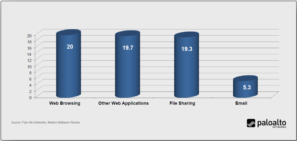
Figure 2-7: Average time to detection by application vector
A sample of new or unknown suspicious traffic must first be captured and identified before a detection signature can be created by security vendors. The new signature must then be downloaded and installed on an organization's endpoints to provide protection.
This process means that some users and networks will be successfully breached by new malware until a new detection signature is created, downloaded, and installed. This reactive model creates a window of opportunity for attackers, leaving endpoints vulnerable — sometimes for weeks or even months — until new malware is suspected, collected, analyzed, and identified. During this time, attackers can infect networks and endpoints.
Another challenge for the signature-based approach is that millions of new malware variations are created each year – on average about 20,000 new forms daily – for which unique signatures must be written, tested, and deployed – after the new malware variation is discovered and sampled. Despite the fact that 70 percent of these millions of malware variations are based on a relatively limited number of malware "families" – numbering just seven in 2005 and increasing to only 20 over the past decade – this reactive approach is not effective for protecting endpoints against modern malware threats.
Also, advanced malware uses techniques such as metamorphism and polymorphism to take advantage of the inherent weaknesses of signature-based detection to avoid being discovered in the wild and to circumvent signatures that have already been created. These techniques are so commonly used that "70 to 90 percent of malware samples [collected] today are unique to a single organization."
Container-based
Container-based endpoint protection wraps a protective virtual barrier around vulnerable processes while they're running. If a process is malicious, the container detects it and shuts it down, preventing it from damaging other legitimate processes or files on the endpoint.
However, the container-based approach typically requires a significant amount of computing resource overhead, and attacks have been demonstrated that circumvent or disable containerbased protection. This approach also requires knowledge of the applications that need to be protected and how they interact with other software components. So a containerization tool will be developed to support certain common applications, but will not be capable of protecting most proprietary or industry-specific software. Even web browser plugins and the like can have problems operating correctly within a container-based environment.
Application whitelisting
Application whitelisting is another endpoint protection technique that is commonly used to prevent end users from running unauthorized applications – including malware – on their endpoints.
Application whitelisting requires a positive control model in which no applications are permitted to run on the endpoint unless they're explicitly permitted by the whitelist policy. In practice, application whitelisting requires a large administrative effort to establish and maintain a list of approved applications. This approach is based on the premise that if you create a list of applications that are specifically allowed and then prevent any other file from executing, you can protect the endpoint. Although this basic functionality can be useful to reduce the attack surface, it is not a comprehensive approach to endpoint security.
Modern trends such as cloud and mobile computing, consumerization, and BYOD/BYOA (all discussed in Section 1.1.1) make application whitelisting extremely difficult to enforce in the enterprise. Also, once an application is whitelisted, it is permitted to run – even if the application has a vulnerability that can be exploited. An attacker can then simply exploit a whitelisted application and have complete control of the target endpoint regardless of the whitelisting. Once the application has been successfully exploited, the attacker can run malicious code while keeping all of the activity in memory. Since no new files are created and no new executables attempt to run, whitelisting software is rendered ineffective against this type of attack.
Anomaly detection
Endpoint security approaches that use mathematical algorithms to detect unusual activity on an endpoint are known as heuristics-based, behavior-based, or anomaly-detection solutions. This approach relies on first establishing an accurate baseline of what is considered "normal" activity. This approach has been around for many years and requires a very large dataset to reduce the number of false positives.
Key Terms:
- In anti-malware, a false positive incorrectly identifies a legitimate file or application as malware. A false negative incorrectly identifies malware as a legitimate file or application. In intrusion detection, a false positive incorrectly identifies legitimate traffic as a threat, and a false negative incorrectly identifies a threat as legitimate traffic.
Anti-spyware
Anti-spyware software is very similar to traditional antivirus software because it uses signatures to look for other forms of malware beyond viruses, such as adware, malicious web application components, and other malicious tools, which share user behaviors without their permission.
Personal firewalls
Network firewalls protect an enterprise network against threats from an external network, such as the internet. However, most traditional port-based network firewalls do little to protect endpoints inside the enterprise network from threats that originate from within the network, such as another device that has been compromised by malware and is propagating throughout the network.
Personal (or host-based) firewalls are commonly installed and configured on laptop and desktop PCs. Personal firewalls typically operate as Layer 7 (Application layer) firewalls that allow or block traffic based on an individual (or group) security policy. Personal firewalls are particularly helpful on laptops used by remote or traveling users that connect their laptop computers directly to the internet, for example, over a public Wi-Fi connection. Also, a personal firewall can control outbound traffic from the endpoint to help prevent the spread of malware from that endpoint. However, note that disabling or otherwise bypassing a personal firewall is a common and basic objective in most advanced malware today.
Windows Firewall is an example of a personal firewall that is installed as part of the Windows desktop or mobile operating system. A personal firewall only protects the endpoint device that it is installed on, but provides an extra layer of protection inside the network.
Host-based Intrusion Prevention Systems (HIPS)
HIPS is another approach to endpoint protection that relies on an agent installed on the endpoint to detect malware. HIPS can be either signature-based or anomaly-based, and is therefore susceptible to the same issues as other signature and anomaly-based endpoint protection approaches.
Also, HIPS software often causes significant performance degradation on endpoints. A recent Palo Alto Networks survey found that 25 percent of respondents indicated HIPS solutions "caused significant end user performance impact."
Mobile device management
Mobile device management (MDM) software provides endpoint security for mobile devices such as smartphones and tablets. Centralized management capabilities for mobile devices provided by MDM include:
- Data loss prevention (DLP): Restrict what type of data can be stored on or transmitted from the device
- Policy enforcement: Require passcodes, enable encryption, lockdown security settings, and prevent jailbreaking or rooting, for example
- Malware protection: Detect and prevent mobile malware
- Software distribution: Remotely install software, including patches and updates over a cellular or Wi-Fi network
- Remote erase/wipe: Securely and remotely delete the complete contents of a lost or stolen device
- Geo-fencing and location services: Restrict specific functionality in the device based on its physical location
Key Terms:
- Jailbreaking refers to hacking an Apple iOS device to gain root-level access to the device. Jailbreaking is sometimes done by end users to allow them to download and install mobile apps without paying for them, from sources, other than the App Store, that are not sanctioned and/or controlled by Apple. Jailbreaking bypasses the security features of the device by replacing the firmware's operating system with a similar, albeit counterfeit version, which makes it vulnerable to malware and exploits. Jailbreaking is known as rooting on Google Android devices.
Cloud, Virtualization, and Storage Security
Cloud computing and virtualization (discussed in Sections 1.1.1, 1.1.3, and 1.1.4) are two important modern computing trends. As data continues to grow exponentially, local and remote storage capacity has become an ever-present challenge, and organizations are increasingly relying on cloud-based storage service offerings. Cloud computing, virtualization, and local and remote storage technologies are discussed in the following sections.
Cloud computing
The U.S. National Institute of Standards and Technology (NIST) defines cloud computing in Special Publication (SP) 800-145 as "a model for enabling ubiquitous, convenient, on-demand network access to a shared pool of configurable computing resources (such as networks, servers, storage, applications, and services) that can be rapidly provisioned and released with minimal management effort or service provider interaction."
NIST defines three distinct cloud computing service models:
- Software as a service (SaaS). Customers are provided access to an application running on a cloud infrastructure. The application is accessible from various client devices and interfaces, but the customer has no knowledge of, and does not manage or control, the underlying cloud infrastructure. The customer may have access to limited user-specific application settings, and security of the customer data is still the responsibility of the customer.
- Platform as a service (PaaS). Customers can deploy supported applications onto the provider's cloud infrastructure, but the customer has no knowledge of, and does not manage or control, the underlying cloud infrastructure. The customer has control over the deployed applications and limited configuration settings for the application-hosting environment. The company owns the deployed applications and data, and it is therefore responsible for the security of those applications and data.
- Infrastructure as a service (IaaS). Customers can provision processing, storage, networks, and other computing resources and deploy and run operating systems and applications. However, the customer has no knowledge of, and does not manage or control, the underlying cloud infrastructure. The customer has control over operating systems, storage, and deployed applications, along with some networking components (for example, host firewalls). The company owns the deployed applications and data, and it is therefore responsible for the security of those applications and data.
NIST also defines these four cloud computing deployment models:
- Public. A cloud infrastructure that is open to use by the general public. It's owned, managed, and operated by a third party (or parties) and it exists on the cloud provider's premises.
- Community. A cloud infrastructure that is used exclusively by a specific group of organizations.
- Private. A cloud infrastructure that is used exclusively by a single organization. It may be owned, managed, and operated by the organization or a third party (or a combination of both), and it may exist on-premises or off-premises.
- Hybrid. A cloud infrastructure that comprise two or more of the aforementioned deployment models, bound by standardized or proprietary technology that enables data and application portability (for example, failover to a secondary data center for disaster recovery or content delivery networks across multiple clouds).
The security risks that threaten your network today do not change when you move to the cloud. The shared responsibility model defines who (customer and/or provider) is responsible for what (related to security) in the public cloud.
In general terms, the cloud provider is responsible for security "of" the cloud, including the physical security of the cloud data centers, and foundational networking, storage, compute, and virtualization services. The cloud customer is responsible for security "in" the cloud, which is further delineated by the cloud service model (see Figure 2-8).
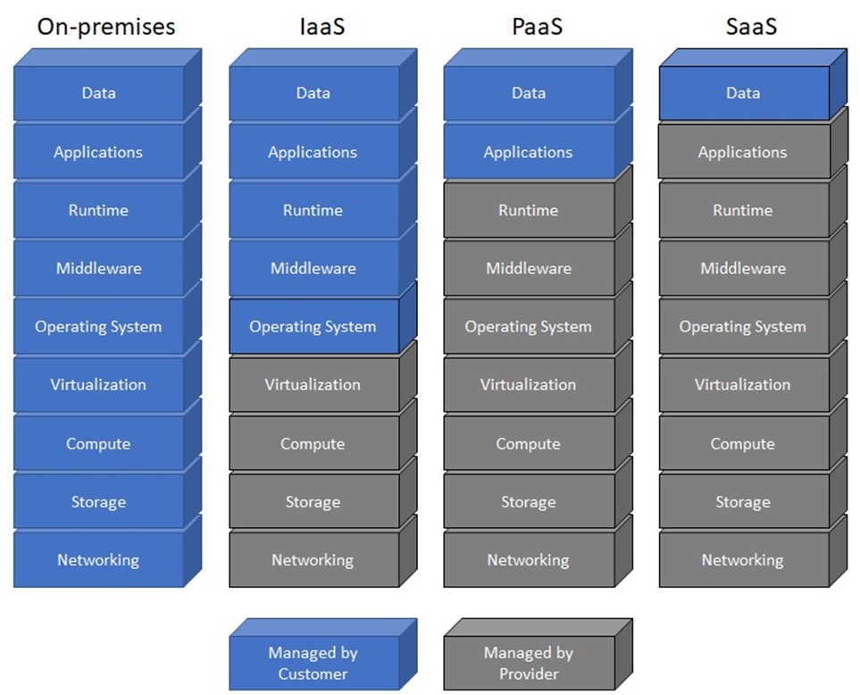
Figure 2-8: The shared responsibility model
For example, in an infrastructure-as-a-service (IaaS) model, the cloud customer is responsible for the security of the operating systems, middleware, run time, applications, and data. In a platform-as-a-service (PaaS) model, the cloud customer is responsible for the security of the applications and data and the cloud provider is responsible for the security of the operating systems, middleware, and run time. In a SaaS model, the cloud customer is responsible only for the security of the data and the cloud provider is responsible for the full stack from the physical security of the cloud data centers to the application. Multitenancy in cloud environments, particularly in SaaS models, means that customer controls and resources are necessarily limited by the cloud provider.
Virtualization
Virtualization technology emulates real — or physical — computing resources, such as servers (compute), storage, networking, and applications. Virtualization allows multiple applications or server workloads to run independently on one or more physical resources.
A hypervisor allows multiple, virtual ("guest") operating systems to run concurrently on a single physical host computer. The hypervisor functions between the computer operating system and the hardware kernel. There are two types of hypervisors:
- Type 1 (native or bare metal). Runs directly on the host computer's hardware
- Type 2 (hosted). Runs within an operating system environment
Key Terms:
- A hypervisor allows multiple, virtual (or guest) operating systems to run concurrently on a single physical host computer.
- A native (also known as a Type 1 or bare metal) hypervisor runs directly on the host computer's hardware.
- A hosted (also known as a Type 2) hypervisor runs within an operating system environment.
Virtualization is a key technology used in data centers and cloud computing to optimize resources. Important security considerations associated with virtualization include:
- Dormant virtual machines (VMs). In many data center and cloud environments, inactive VMs are routinely (often automatically) shut down when they are not in use. VMs that are shut down for extended periods of time (weeks or months) may be inadvertently missed when anti-malware updates and security patches are applied.
- Hypervisor vulnerabilities. In addition to vulnerabilities within the hosted applications, VMs, and other resources in a virtual environment, the hypervisor itself may be vulnerable, which can expose hosted resources to attack.
- Intra-VM communications. Network traffic between virtual hosts, particularly on a single physical server, may not traverse a physical switch. This lack of visibility increases troubleshooting complexity and can increase security risks because of inadequate monitoring and logging capabilities.
- VM sprawl. Virtual environments can grow quickly, leading to a breakdown in change management processes and exacerbating security issues such as dormant VMs, hypervisor vulnerabilities, and intra-VM communications.
Local and remote storage
Three basic storage technologies commonly are used in local and remote storage:
- Block. In data storage, a block is a sequence of bits or bytes of a fixed length or size, for example, 512 bytes. Devices such as computers, servers, and storage area networks (SANs) access block-based storage through various interfaces including advanced technology attachment (ATA), Fibre Channel Protocol (FCP), Internet SCSI (iSCSI), serial attached SCSI (SAS), serial ATA (SATA), and small computer system interface (SCSI). Before you can use block-based storage, you must create a volume, install an operating system, and mount (or attach to) the storage device.
- File. File-based storage systems, such as network-attached storage (NAS), typically run their own operating system and manage access control and permissions using inodes. File-based storage systems are accessed using protocols such as Common Internet File System (CIFS), Network File System (NFS), and Server Message Block (SMB). File-based storage typically requires mapping a drive letter or network path to the storage device.
- Object. Object-based storage systems use variable-sized data containers, known as objects, which are organized into a flat address space rather than a hierarchical file system such as a directory-based structure. Object-based storage systems are used to manage large content repositories containing several petabytes of data and billions of objects. Users typically access object-based storage using a web browser or an application that uses an HTTP interface to interact with the storage device.
Key Terms:
- Inodes are data structures that store information about files and directories in a file-based storage system, but not the filenames or data content itself.
2.9 Networking Concepts
Important networking and operations concepts covered in this section include server and system administration, directory services, troubleshooting, IT best practices, and technical support.
2.9.1 Server and system administration
Server and system administrators perform a variety of important tasks in a network environment. Typical server and system administration tasks include:
- Account provisioning and de-provisioning
- Managing account permissions
- Installing and maintaining server software
- Maintaining and optimizing servers, applications, databases (may be assigned to a database administrator), and network devices (may be assigned to a network administrator) and security devices (may be assigned to a security administrator)
- Installing security patches
- Managing system and data backup and recovery
- Monitoring network communication and server logs
- Troubleshooting and resolving server and system issues
Patch management
New software vulnerabilities and exploits are discovered each year, requiring diligent software patch management by system and security administrators in every organization.
However, patch management only protects an organization's endpoints after a vulnerability has been discovered and the patch installed. Delays of days, weeks, or longer are inevitable because security patches for newly discovered vulnerabilities must be developed, distributed, tested, and deployed. Although patch management is an important aspect of any information security program, like signature-based anti-malware detection, it is an endless race against time that offers no protection against zero-day exploits.
Configuration management
Configuration management is the formal process used by organizations to define and maintain standard configurations for applications, devices, and systems throughout their lifecycle. For example, a particular desktop PC model may be configured by an organization with specific security settings such as enabling whole disk encryption and disabling USB ports. Within the desktop operating system, security settings such as disabling unneeded and risky services (for example, FTP and Telnet) may be configured. Maintenance of standard configurations on applications, devices, and systems used by an organization helps to reduce risk exposure and improve security posture.
Directory services
A directory service is a database that contains information about users, resources, and services in a network. The directory service associates users and network permissions to control who has access to which resources and services on the network. Directory services include:
- Active Directory. A centralized directory service developed by Microsoft for Windows networks to provide authentication and authorization of users and network resources. Active Directory uses the lightweight directory access protocol (LDAP), Kerberos, and the Domain Name System (DNS, discussed in Section 2.1.5)
- lightweight directory access protocol (LDAP). An IP-based client-server protocol that provides access and manages directory information in TCP/IP networks
Key Terms:
- Kerberos is a ticket-based authentication protocol in which "tickets" are used to identify network users.
Structured host and network troubleshooting
A network or segment of a network that goes down could have a negative impact on your organization or business. Network administrators should use a systematic process to troubleshoot network problems when they occur to restore the network to full production as quickly as possible without causing new issues or introducing new security vulnerabilities. The troubleshooting process performed by a network administrator to resolve network problems quickly and efficiently is a highly sought skill in IT.
Two of the most important troubleshooting tasks a network administrator performs occur long before a network problem occurs: baselining and documenting the network.
A baseline provides quantifiable metrics that are periodically measured with various network performance monitoring tools, protocol analyzers, and packet sniffers. Important metrics might include application response times, server memory and processor utilization, average and peak network throughput, and storage input/output operations per second. These baseline metrics provide an important snapshot of "normal" network operations to help network administrators identify impending problems, troubleshoot current problems, and know when a problem has been fully resolved.
Network documentation should include logical and physical diagrams, application data flows, change management logs, user and administration manuals, and warranty and support information. Network baselines and documentation should be updated any time a significant change to the network occurs, and as part of the change management process of an organization.
Many formal multi-step troubleshooting methodologies have been published and various organizations or individual network administrators may have their own preferred method.
Generally speaking, troubleshooting consists of these steps:
- Discover the problem.
- Evaluate system configuration against the baseline.
- Track possible solutions.
- Execute a plan.
- Check results.
- Verify solution. (If unsuccessful, go back to Step 2; if successful, proceed to Step 7.)
- Deploy positive solution.
Troubleshooting host and network connectivity problems typically starts with analyzing the scope of the problem and identifying the devices and services that are affected. Problems with local hosts are typically much easier to assess and remedy than problems that affect a network segment or service. For an individual device that loses network connectivity, the problem sometimes can be easily resolved by simply restarting the device. However, problems with integrated or shared services, for example, web or file services, can be complex, and restarting a service or rebooting a device may actually compound the problem. Connectivity problems may be intermittent or difficult to trace, so it's important that your troubleshooting processes follow an approved or standardized methodology.
The OSI model (discussed in Section 2.3.1) provides a logical model for troubleshooting complex host and network issues. Depending on the situation, you might use the bottom-up, top-down, or "divide and conquer" approach discussed in the following paragraphs when you use the OSI model to guide your troubleshooting efforts. In other situations, you might make an "educated guess" about the source of the issue and begin investigating at the corresponding layer of the OSI model, or use the substitution method (replacing a bad component with a known good component) to quickly identify and isolate the cause of the issue.
When you use a bottom-up approach to diagnose connectivity problems, you begin at the Physical layer of the OSI model by verifying network connections and device availability. For example, a wireless device may have power to the antenna or transceiver temporarily turned off. Or, a wireless access point may have lost power because a circuit breaker may have been tripped offline or a fuse may have been blown. Similarly, a network cable connection may be loose or the cable may be damaged. Thus, before you begin inspecting service architectures, you should start with the basics: confirm physical connectivity.
Moving up to the Data Link layer, you verify data link architectures, such as compatibility with a particular standard or frame type. Although Ethernet is a predominant LAN network standard, devices that roam (such as wireless devices) sometimes automatically switch between Wi-Fi, Bluetooth, and Ethernet networks. Wireless networks usually have specified encryption standards and keys. Connectivity may be lost because a network device or service has been restored to a previous setting and the device is not responding to endpoint requests that are using different settings. Firewalls and other security policies may also be interfering with connection requests. You should never disable firewalls, but in a controlled network environment with proper procedures established, you may find that temporarily disabling or bypassing a security appliance resolves a connectivity issue. The remedy then is to properly configure security services to allow the required connections.
Various connectivity problems may also occur at the Network layer. Important troubleshooting steps include confirming proper network names and addresses. Devices may have improperly assigned IP addresses that are causing routing issues or IP address conflicts on the network. A device may have an improperly configured IP address because it cannot communicate with a
DHCP server on the network. Similarly, networks have different identities, such as wireless SSIDs, domain names, and workgroup names. Another common problem exists when a particular network has conflicting names or addresses. Issues with DNS name resolvers may be caused by DNS caching services or connection to the wrong DNS servers. The Internet Control Message Protocol (ICMP) is used for network control and diagnostics at the Network layer of the OSI model. Commonly used ICMP commands include ping and traceroute. These two simple, but powerful commands (and other ICMP commands and options) are some of the most commonly used tools for troubleshooting network connectivity issues. You can run ICMP commands using the command line interface on computers, servers, routers, switches, and many other networked devices.
At the Transport layer, communications are more complex. Latency and network congestion can interfere with communications that depend on timely acknowledgments and handshakes. time-to-live (TTL) values sometimes have to be extended in the network service architecture to allow for slower response times during peak network traffic hours. Similar congestion problems can occur when new services are added to an existing network, or when a local device triggers a prioritized service, such as a backup or antivirus scan.
Session layer settings can also be responsible for dropped network connections. For example, devices that automatically go into a power standby mode ("sleep") may have expired session tokens that fail when the device attempts to resume connectivity. At the server, failover communications or "handshake" negotiations with one server may not translate to other clustered servers. Sessions may have to be restarted.
Presentation layer conflicts are often related to changes in encryption keys or updates to service architectures that are not supported by different client devices. For example, an older browser may not interoperate with a script or a new encoding standard.
Application layer network connectivity problems are extremely common. Many applications may conflict with other apps. Apps also may have caching or corrupted files that can be remedied only by uninstalling and reinstalling, or updating to a newer version. Some apps also require persistent connections to updater services or third parties, and network security settings may prevent those connections from being made.
Other troubleshooting steps may include searching log files for anomalies and significant events, verifying that certificates or proper authentication protocols are installed and available, verifying encryption settings, clearing application caches, updating applications, and, for endpoints, removing and reinstalling an application. Search vendor-supported support sites and forums and frequently asked questions (FAQ) pages before you make changes to installed services. You also must be aware of any service-level agreements (SLAs) that your organization must meet.
Always follow proper troubleshooting steps, keep accurate records of any changes that you attempt, document your changes, and publish any remedies so that others can learn from your troubleshooting activities.
ITIL fundamentals
ITIL (formerly known as the Information Technology Infrastructure Library) is a five-volume set of IT service management best practices:
- Service Strategy. Addresses IT services strategy management, service portfolio management, IT services financial management, demand management, and business relationship management
- Service Design. Addresses design coordination, service catalog management, service level management, availability management, capacity management, IT service continuity management, information security management system, and supplier management
- Service Transition. Addresses transition planning and support, change management, service asset and configuration management, release and deployment management, service validation and testing, change evaluation, and knowledge management
- Service Operation. Addresses event management, incident management, service request fulfillment, problem management, and access management
- Continual Service Improvement. Defines a seven-step process for improvement initiatives, including identifying the strategy, defining what will be measured, gathering the data, processing the data, analyzing the information and data, presenting and using the information, and implementing the improvement
Help desk and technical support
An important function in any IT department is the help desk (or technical support). The help desk is the IT department's liaison to an organization's users (or customers).
Help desks are commonly organized in multiple tiers, for example, User Support (tier 1), Desktop Support (tier 2), Network Support (tier 3). User issues that cannot be resolved at tier 1 are escalated to the appropriate tier. Typical performance measures for a help desk include service-level agreements (SLAs), wait times, first-call resolution, and mean-time-to-repair (MTTR).
Glossary
- access point (AP): See wireless access point (AP).
- Address Resolution Protocol (ARP): A protocol that translates a logical address, such as an IP address, to a physical MAC address. The Reverse Address Resolution Protocol (RARP) translates a physical MAC address to a logical address. See also IP address, media access control (MAC) address, and Reverse Address Resolution Protocol (RARP).
- Advanced Encryption Standard (AES): A symmetric block cipher based on the Rijndael cipher.
- AES: See Advanced Encryption Standard (AES).
- AP: See wireless access point (AP).
- API: See application programming interface (API).
- application programming interface (API): A set of routines, protocols, and tools for building software applications and integrations.
- application whitelisting: A technique used to prevent unauthorized applications from running on an endpoint. Authorized applications are manually added to a list that is maintained on the endpoint. If an application is not on the whitelist, it cannot run on the endpoint. However, if it is on the whitelist the application can run, regardless of whether vulnerabilities or exploits are present within the application.
- ARP: See Address Resolution Protocol (ARP).
- AS: See autonomous system (AS).
- attack vector: A path or tool that an attacker uses to target a network.
- authoritative DNS server: The system of record for a given domain. See also Domain Name System (DNS).
- autonomous system (AS): A group of contiguous IP address ranges under the control of a single internet entity. Individual autonomous systems are assigned a 16-bit or 32-bit AS number (ASN) that uniquely identifies the network on the internet. ASNs are assigned by the Internet Assigned Numbers Authority (IANA). See also Internet Protocol (IP) address and Internet Assigned Numbers Authority (IANA).
- bare metal hypervisor: See native hypervisor.
- BES: See bulk electric system (BES).
- boot sector: Contains machine code that is loaded into an endpoint's memory by firmware during the startup process, before the operating system is loaded.
- boot sector virus: Targets the boot sector or master boot record (MBR) of an endpoint's storage drive or other removable storage media. See also boot sector and master boot record (MBR).
- bot: Individual endpoints that are infected with advanced malware that enables an attacker to take control of the compromised endpoint. Also known as a zombie. See also botnet and malware.
- botnet: A network of bots (often tens of thousands or more) working together under the control of attackers using numerous command-and-control (C&C) servers. See also bot.
- bridge: A wired or wireless network device that extends a network or joins separate network segments.
- bring your own apps (BYOA): Closely related to BYOD, BYOA is a policy trend in which organizations permit end users to download, install, and use their own personal apps on mobile devices, primarily smartphones and tablets, for work-related purposes. See also bring your own device (BYOD).
- bring your own device (BYOD): A policy trend in which organizations permit end users to use their own personal devices, primarily smartphones and tablets, for work-related purposes. BYOD relieves organizations from the cost of providing equipment to employees, but creates a management challenge because of the vast number and type of devices that must be supported. See also bring your own apps (BYOA).
- broadband cable: A type of high-speed internet access that delivers different upload and download data speeds over a shared network medium. The overall speed varies depending on the network traffic load from all the subscribers on the network segment.
- broadcast domain: The portion of a network that receives broadcast packets sent from a node in the domain.
- bulk electric system (BES): The large interconnected electrical system, consisting of generation and transmission facilities (among others), that comprises the "power grid."
- bus (or linear bus) topology: A LAN topology in which all nodes are connected to a single cable (the backbone) that is terminated on both ends. In the past, bus networks were commonly used for very small networks because they were inexpensive and relatively easy to install, but today bus topologies are rarely used. The cable media has physical limitations (the cable length), the backbone is a single point of failure (a break anywhere on the network affects the entire network), and tracing of a fault in a large network can be extremely difficult. See also local-area network (LAN).
- BYOA: See bring your own apps (BYOA). BYOD: See bring your own device (BYOD).
- child process: In multitasking operating systems, a subprocess created by a parent process that is currently running on the system.
- CIDR: See classless inter-domain routing (CIDR).
- CIP: See Critical Infrastructure Protection (CIP).
- circuit-switched network: A network in which a dedicated physical circuit path is established, maintained, and terminated between the sender and receiver across a network for each communications session.
- classless inter-domain routing (CIDR): A method for allocating IP addresses and IP routing that replaces classful IP addressing (for example, Class A, B, and C networks) with classless IP addressing. See also Internet Protocol (IP) address.
- collision domain: A network segment on which data packets may collide with each other during transmission.
- consumerization: A computing trend that describes the process that occurs as end users increasingly find personal technology and apps that are more powerful or capable, more convenient, less expensive, quicker to install, and easier to use, than enterprise IT solutions.
- convergence: The time required for all routers in a network to update their routing tables with the most current routing information about the network.
- covered entity: Defined by HIPAA as a healthcare provider that electronically transmits PHI (such as doctors, clinics, psychologists, dentists, chiropractors, nursing homes, and pharmacies), a health plan (such as a health insurance company, health maintenance organization, company health plan, or government program including Medicare, Medicaid, military and veterans' healthcare), or a healthcare clearinghouse. See also Health Insurance Portability and Accountability Act (HIPAA) and protected health information (PHI).
- CRC: See cyclic redundancy check (CRC).
- Critical Infrastructure Protection (CIP): Cybersecurity standards defined by NERC to protect the physical and cyber assets necessary to operate the bulk electric system (BES). See also bulk electric system (BES) and North American Electric Reliability Corporation (NERC).
- Cybersecurity Enhancement Act of 2014: A U.S. regulation that provides an ongoing, voluntary public-private partnership to improve cybersecurity and to strengthen cybersecurity research and development, workforce development and education, and public awareness and preparedness.
- Cybersecurity Information Sharing Act (CISA): A U.S. regulation that enhances information sharing about cybersecurity threats by allowing internet traffic information to be shared between the U.S. government and technology and manufacturing companies.
- cyclic redundancy check (CRC): A checksum used to create a message profile. The CRC is recalculated by the receiving device. If the recalculated CRC doesn't match the received CRC, the packet is dropped and a request to resend the packet is transmitted back to the device that sent the packet.
- data encapsulation: A process in which protocol information from the OSI or TCP/IP layer immediately above is wrapped in the data section of the OSI or TCP/IP layer immediately below. Also referred to as data hiding. See also Open Systems Interconnection (OSI) reference model and Transmission Control Protocol/Internet Protocol (TCP/IP) model. data hiding: See data encapsulation.
- DDOS: See distributed denial-of-service (DDOS).
- default gateway: A network device, such as a router or switch, to which an endpoint sends network traffic when a specific destination IP address is not specified by an application or service, or when the endpoint does not know how to reach a specified destination. See also router and switch.
- DevOps: The culture and practice of improved collaboration between application development and IT operations teams.
- DHCP: See Dynamic Host Configuration Protocol (DHCP).
- digital subscriber line (DSL): A type of high-speed internet access that delivers different upload and download data speeds. The overall speed depends on the distance from the home or business location to the provider's central office (CO).
- distributed denial-of-service (DDOS): A type of cyberattack in which extremely high volumes of network traffic such as packets, data, or transactions are sent to the target victim's network to make their network and systems (such as an e-commerce website or other web application) unavailable or unusable.
- DLL: See dynamic-link library (DLL).
- DNS: See Domain Name System (DNS).
- domain name registrar: An organization that is accredited by a top-level domain (TLD) registry to manage domain name registrations. See also top-level domain (TLD).
- Domain Name System (DNS): A hierarchical distributed database that maps the fully qualified domain name (FQDN) for computers, services, or any resource connected to the internet or a private network to an IP address. See also fully qualified domain name (FQDN).
- drive-by-download: A software download, typically malware, that happens without a user's knowledge or permission.
- DSL: See digital subscriber line (DSL).
- Dynamic Host Configuration Protocol (DHCP): A network management protocol that dynamically assigns (leases) IP addresses and other network configuration parameters (such as default gateway and Domain Name System [DNS] information) to devices on a network. See also default gateway and Domain Name System (DNS).
- dynamic-link library (DLL): A type of file used in Microsoft operating systems that enables multiple programs to simultaneously share programming instructions contained in a single file to perform specific functions.
- EAP: See Extensible Authentication Protocol (EAP).
- EAP-TLS: See Extensible Authentication Protocol Transport Layer Security (EAP-TLS).
- EHR: See electronic health record (EHR).
- electronic health record (EHR): As defined by HealthIT.gov, an EHR "goes beyond the data collected in the provider's office and include[s] a more comprehensive patient history. EHR data can be created, managed, and consulted by authorized providers and staff from across more than one healthcare organization."
- electronic medical record (EMR): As defined by HealthIT.gov, an EMR "contains the standard medical and clinical data gathered in one provider's office."
- EMR: See electronic medical record (EMR).
- endpoint: A computing device such as a desktop or laptop computer, handheld scanner, pointof-sale (POS) terminal, printer, satellite radio, security or videoconferencing camera, selfservice kiosk, server, smart meter, smart TV, smartphone, tablet, or Voice over Internet Protocol (VoIP) phone. Although endpoints can include servers and network equipment, the term is generally used to describe end user devices.
- Enterprise 2.0: A term introduced by Andrew McAfee and defined as "the use of emergent social software platforms within companies, or between companies and their partners or customers." See also Web 2.0.
- exclusive or (XOR): A Boolean operator in which the output is true only when the inputs are different (for example, TRUE and TRUE equals FALSE, but TRUE and FALSE equals TRUE).
- exploit: A small piece of software code, part of a malformed data file, or a sequence (string) of commands, that leverages a vulnerability in a system or software, causing unintended or unanticipated behavior in the system or software.
- Extensible Authentication Protocol (EAP): A widely used authentication framework that includes about 40 different authentication methods.
- Extensible Authentication Protocol Transport Layer Security (EAP-TLS): An Internet Engineering Task Force (IETF) open standard that uses the Transport Layer Security (TLS) protocol in Wi-Fi networks and PPP connections. See also Internet Engineering Task Force (IETF), point-to-point protocol (PPP), and Transport Layer Security (TLS).
- Extensible Markup Language (XML): A programming language specification that defines a set of rules for encoding documents in a human-readable and machine-readable format.
- false negative: In anti-malware, malware that is incorrectly identified as a legitimate file or application. In intrusion detection, a threat that is incorrectly identified as legitimate traffic. See also false positive.
- false positive: In anti-malware, a legitimate file or application that is incorrectly identified as malware. In intrusion detection, legitimate traffic that is incorrectly identified as a threat. See also false negative.
- favicon ("favorite icon"): A small file containing one or more small icons associated with a particular website or webpage.
- Federal Exchange Data Breach Notification Act of 2015: A U.S. regulation that further strengthens HIPAA by requiring health insurance exchanges to notify individuals whose personal information has been compromised as the result of a data breach as soon as possible, but no later than 60 days after breach discovery. See also Health Insurance Portability and Accountability Act (HIPAA).
- Federal Information Security Management Act (FISMA): See Federal Information Security Modernization Act (FISMA).
- Federal Information Security Modernization Act (FISMA): A U.S. law that implements a comprehensive framework to protect information systems used in U.S. federal government agencies. Known as the Federal Information Security Management Act prior to 2014.
- fiber optic: Technology that converts electrical data signals to light and delivers constant data speeds in the upload and download directions over a dedicated fiber optic cable medium. Fiber optic technology is much faster and more secure than other types of network technology.
- Financial Services Modernization Act of 1999: See Gramm-Leach-Bliley Act (GLBA).
- FISMA: See Federal Information Security Modernization Act (FISMA).
- floppy disk: A removable magnetic storage medium commonly used from the mid-1970s until about 2007, when it was largely replaced by removable USB storage devices.
- flow control: A technique used to monitor the flow of data between devices to ensure that a receiving device, which may not necessarily be operating at the same speed as the transmitting device, doesn't drop packets.
- fully qualified domain name (FQDN): The complete domain name for a specific computer, service, or resource connected to the internet or a private network.
- GDPR: See General Data Protection Regulation (GDPR).
- General Data Protection Regulation (GDPR): A European Union (EU) regulation that applies to any organization that does business with EU citizens. It strengthens data protection for EU citizens and addresses the export of personal data outside the EU.
- Generic Routing Encapsulation (GRE): A tunneling protocol developed by Cisco Systems that can encapsulate various network layer protocols inside virtual point-to-point links.
- GLBA: See Gramm-Leach-Bliley Act (GLBA).
- Gramm-Leach-Bliley Act (GLBA): A U.S. law that requires financial institutions to implement privacy and information security policies to safeguard the non-public personal information of clients and consumers. Also known as the Financial Services Modernization Act of 1999.
- GRE: See Generic Routing Encapsulation (GRE).
- hacker: Term originally used to refer to anyone with highly specialized computing skills, without connoting good or bad purposes. However, common misuse of the term has redefined a hacker as someone that circumvents computer security with malicious intent, such as a cybercriminal, cyberterrorist, or hacktivist.
- hash signature: A cryptographic representation of an entire file or program's source code.
- Health Insurance Portability and Accountability Act (HIPAA): A U.S. law that defines data privacy and security requirements to protect individuals' medical records and other personal health information. See also covered entity and protected health information (PHI).
- heap spray: A technique used to facilitate arbitrary code execution by injecting a certain sequence of bytes into the memory of a target process.
- hextet: A group of four 4-bit hexadecimal digits in a 128-bit IPv6 address. See also Internet Protocol (IP) address.
- high-order bits: The first four bits in a 32-bit IPv4 address octet. See also Internet Protocol (IP) address, octet, and low-order bits.
- HIPAA: See Health Insurance Portability and Accountability Act (HIPAA).
- hop count: The number of router nodes that a packet must pass through to reach its destination.
- hosted hypervisor: A hypervisor that runs within an operating system environment. Also known as a Type 2 hypervisor. See also hypervisor and native hypervisor.
- HTTP: See Hypertext Transfer Protocol (HTTP). HTTPS: See Hypertext Transfer Protocol Secure (HTTPS).
- hub (or concentrator): A device used to connect multiple networked devices together on a local-area network (LAN).
- Hypertext Transfer Protocol (HTTP): An application protocol used to transfer data between web servers and web browsers.
- Hypertext Transfer Protocol Secure (HTTPS): A secure version of HTTP that uses Secure Sockets Layer (SSL) or Transport Layer Security (TLS) encryption. See also Secure Sockets Layer (SSL) and Transport Layer Security (TLS).
- hypervisor: Technology that allows multiple, virtual (or guest) operating systems to run concurrently on a single physical host computer.
- IaaS: See infrastructure as a service (IaaS).
- IANA: See Internet Assigned Numbers Authority (IANA).
- IETF: See Internet Engineering Task Force (IETF).
- indicator of compromise (IoC): A network or operating system (OS) artifact that provides a high level of confidence that a computer security incident has occurred.
- infrastructure as a service (IaaS). A cloud computing service model in which customers can provision processing, storage, networks, and other computing resources and deploy and run operating systems and applications. However, the customer has no knowledge of, and does not manage or control, the underlying cloud infrastructure. The customer has control over operating systems, storage, and deployed applications, and some networking components (for example, host firewalls). The company owns the deployed applications and data, and it is therefore responsible for the security of those applications and data.
- initialization vector (IV): A random number used only once in a session, in conjunction with an encryption key, to protect data confidentiality. Also known as a nonce.
- inodes: A data structure used to store information about files and directories in a file-based storage system, but not the filenames or data content itself.
- Internet Assigned Numbers Authority (IANA): A private, nonprofit U.S. corporation that oversees global IP address allocation, autonomous system (AS) number allocation, root zone management in the Domain Name System (DNS), media types, and other Internet Protocolrelated symbols and internet numbers. See also autonomous system (AS) and Domain Name System (DNS).
- Internet Engineering Task Force (IETF): An open international community of network designers, operators, vendors, and researchers concerned with the evolution of the internet architecture and the smooth operation of the internet.
- Internet Protocol (IP) address: A 32-bit or 128-bit identifier assigned to a networked device for communications at the Network layer of the OSI model or the Internet layer of the TCP/IP model. See also Open Systems Interconnection (OSI) reference model and Transmission Control Protocol/Internet Protocol (TCP/IP) model.
- intranet: A private network that provides information and resources – such as a company directory, human resources policies and forms, department or team files, and other internal information – to an organization's users. Like the internet, an intranet uses the HTTP and/or HTTPS protocols, but access to an intranet is typically restricted to an organization's internal users. Microsoft SharePoint is a popular example of intranet software. See also Hypertext Transfer Protocol (HTTP) and Hypertext Transfer Protocol Secure (HTTPS).
- IoC: See indicator of compromise (IoC).
- IP address: See Internet Protocol (IP) address.
- IP telephony: See Voice over Internet Protocol (VoIP).
- IV: See initialization vector (IV).
- jailbreaking: Hacking an Apple iOS device to gain root-level access to the device. This hacking is sometimes done by end users to allow them to download and install mobile apps without paying for them, from sources, other than the App Store, that are not sanctioned and/or controlled by Apple. Jailbreaking bypasses the security features of the device by replacing the firmware's operating system with a similar, albeit counterfeit version, which makes the device vulnerable to malware and exploits. See also rooting.
- Kerberos: A ticket-based authentication protocol in which "tickets" are used to identify network users.
- LAN: See local-area network (LAN).
- least privilege: A network security principle in which only the permission or access rights necessary to perform an authorized task are granted.
- least significant bit: The last bit in a 32-bit IPv4 address octet. See also Internet Protocol (IP) address, octet, and most significant bit. linear bus topology: See bus topology.
- local-area network (LAN): A computer network that connects laptop and desktop computers, servers, printers, and other devices so that applications, databases, files and file storage, and other networked resources can be shared across a relatively small geographic area such as a floor, a building, or a group of buildings.
- low-order bits: The last four bits in a 32-bit IPv4 address octet. See also Internet Protocol (IP) address, octet, and high-order bits.
- MAC address: See media access control (MAC) address.
- malware: Malicious software or code that typically damages, takes control of, or collects information from an infected endpoint. Malware broadly includes viruses, worms, Trojan horses (including Remote Access Trojans, or RATs), anti-AV, logic bombs, back doors, rootkits, bootkits, spyware, and (to a lesser extent) adware.
- master boot record (MBR): The first sector on a computer hard drive, containing information about how the logical partitions (or file systems) are organized on the storage media, and an executable boot loader that starts up the installed operating system.
- MBR: See master boot record (MBR).
- media access control (MAC) address: A unique 48-bit or 64-bit identifier assigned to a network interface controller (NIC) for communications at the Data Link layer of the OSI model. See also Open Systems Interconnection (OSI) reference model.
- metamorphism: A programming technique used to alter malware code with every iteration, to avoid detection by signature-based anti-malware software. Although the malware payload changes with each iteration – for example, by using a different code structure or sequence, or inserting garbage code to change the file size – the fundamental behavior of the malware payload remains unchanged. Metamorphism uses more advanced techniques than polymorphism. See also polymorphism.
- Microsoft Challenge-Handshake Authentication Protocol (MS-CHAP): A protocol used to authenticate Microsoft Windows-based workstations using a challenge-response mechanism to authenticate PPTP connections without sending passwords. See also point-to-point tunneling protocol (PPTP).
- most significant bit: The first bit in a 32-bit IPv4 address octet. See also Internet Protocol (IP) address, octet, and least significant bit.
- MS-CHAP: See Microsoft Challenge-Handshake Authentication Protocol (MS-CHAP).
- mutex: A program object that allows multiple program threads to share the same resource, such as file access, but not simultaneously.
- NAT: See network address translation (NAT).
- National Cybersecurity Protection Advancement Act of 2015: A U.S. regulation that amends the Homeland Security Act of 2002 to enhance multi-directional sharing of information related to cybersecurity risks and strengthens privacy and civil liberties protections.
- native hypervisor: A hypervisor that runs directly on the host computer hardware. Also known as a Type 1 or bare metal hypervisor. See also hypervisor and hosted hypervisor.
- NERC: See North American Electric Reliability Corporation (NERC).
- network address translation (NAT): A technique used to virtualize IP addresses by mapping private, non-routable IP addresses assigned to internal network devices to public IP addresses.
- Network and Information Security (NIS) Directive: A European Union (EU) directive that imposes network and information security requirements for banks, energy companies, healthcare providers and digital service providers, among others. NIS Directive: See Network and Information Security (NIS) Directive. nonce: See initialization vector (IV).
- North American Electric Reliability Corporation (NERC): A not-for-profit international regulatory authority responsible for assuring the reliability of the bulk electric system (BES) in the continental United States, Canada, and the northern portion of Baja California, Mexico. See also bulk electric system (BES) and Critical Infrastructure Protection (CIP).
- obfuscation: A programming technique used to render code unreadable. It can be implemented using a simple substitution cipher, such as an exclusive or (XOR) operation, or more sophisticated encryption algorithms, such as the Advanced Encryption Standard (AES). See also Advanced Encryption Standard (AES), exclusive or (XOR), and packer.
- octet: A group of 8 bits in a 32-bit IPv4 address. See Internet Protocol (IP) address.
- one-way (hash) function: A mathematical function that creates a unique representation (a hash value) of a larger set of data in a manner that is easy to compute in one direction (input to output), but not in the reverse direction (output to input). The hash function can't recover the original text from the hash value. However, an attacker could attempt to guess what the original text was and see if it produces a matching hash value.
- Open Systems Interconnection (OSI) reference model: A seven-layer networking model consisting of the Application (Layer 7 or L7), Presentation (Layer 6 or L6), Session (Layer 5 or L5), Transport (Layer 4 or L4), Network (Layer 3 or L3), Data Link (Layer 2 or L2), and Physical
- (Layer 1 or L1) layers. Defines standard protocols for communication and interoperability using a layered approach in which data is passed from the highest layer (application) downward through each layer to the lowest layer (physical), then transmitted across the network to its destination, then passed upward from the lowest layer to the highest layer. See also data encapsulation.
- optical carrier: A standard specification for the transmission bandwidth of digital signals on Synchronous Optical Networking (SONET) fiber optic networks. Optical carrier transmission rates are designated by the integer value of the multiple of the base rate (51.84Mbps). For example, OC-3 designates a 155.52Mbps (3 x 51.84) network and OC-192 designates a 9953.28Mbps (192 x 51.84) network.
- OSI model: See Open Systems Interconnection (OSI) reference model.
- PaaS: See platform as a service (PaaS).
- packer: A software tool that can be used to obfuscate code by compressing a malware program for delivery, then decompressing it in memory at run time. See also obfuscation.
- packet capture (pcap): A traffic intercept of data packets that can be used for analysis.
- packet-switched network: A network in which devices share bandwidth on communications links to transport packets between a sender and receiver across a network.
- PAP: See Password Authentication Protocol (PAP).
- Password Authentication Protocol (PAP): An authentication protocol used by PPP to validate users with an unencrypted password. See also point-to-point protocol (PPP).
- Payment Card Industry Data Security Standards (PCI DSS): A proprietary information security standard mandated and administered by the PCI Security Standards Council (SSC), and applicable to any organization that transmits, processes, or stores payment card (such as debit and credit cards) information. See also PCI Security Standards Council (SSC). pcap: See packet capture (pcap).
- PCI: See Payment Card Industry Data Security Standards (PCI DSS).
- PCI DSS: See Payment Card Industry Data Security Standards (PCI DSS).
- PCI Security Standards Council (SSC): A group comprising Visa, MasterCard, American Express, Discover, and JCB that maintains, evolves, and promotes PCI DSS. See also Payment Card Industry Data Security Standards (PCI DSS).
- PDU: See protocol data unit (PDU).
- Personal Information Protection and Electronic Documents Act (PIPEDA): A Canadian privacy law that defines individual rights with respect to the privacy of their personal information, and governs how private sector organizations collect, use, and disclose personal information in the course of business.
- Personally Identifiable Information (PII): Defined by the U.S. National Institute of Standards and Technology (NIST) as "any information about an individual maintained by an agency, including (1) any information that can be used to distinguish or trace an individual's identity… and (2) any other information that is linked or linkable to an individual…."
- pharming: A type of attack that redirects a legitimate website's traffic to a fake site.
- PHI: See protected health information (PHI).
- PII: See Personally Identifiable Information (PII).
- PIPEDA: See Personal Information Protection and Electronic Documents Act (PIPEDA).
- PKI: See public key infrastructure (PKI).
- platform as a service (PaaS): A cloud computing service model in which customers can deploy supported applications onto the provider's cloud infrastructure, but the customer has no knowledge of, and does not manage or control, the underlying cloud infrastructure. The customer has control over the deployed applications and limited configuration settings for the application-hosting environment. The company owns the deployed applications and data, and it is therefore responsible for the security of those applications and data.
- PoE: See power over Ethernet (PoE).
- point-to-point protocol (PPP): A Layer 2 (Data Link) protocol layer used to establish a direct connection between two nodes.
- point-to-point tunneling protocol (PPTP): An obsolete method for implementing virtual private networks, with many known security issues, that uses a TCP control channel and a GRE tunnel to encapsulate PPP packets. See also Transmission Control Protocol (TCP), Generic Routing Encapsulation (GRE), and point-to-point protocol (PPP).
- polymorphism: A programming technique used to alter a part of malware code with every iteration, to avoid detection by signature-based anti-malware software. For example, an encryption key or decryption routine may change with every iteration, but the malware payload remains unchanged. See also metamorphism.
- power over Ethernet (PoE): A network standard that provides electrical power to certain network devices over Ethernet cables.
- PPP: See point-to-point protocol (PPP).
- PPTP: See point-to-point tunneling protocol (PPTP).
- pre-shared key (PSK): A shared secret, used in symmetric key cryptography that has been exchanged between two parties communicating over an encrypted channel.
- promiscuous mode: Refers to Ethernet hardware used in computer networking, typically a network interface card (NIC), that receives all traffic on a network segment, even if the traffic is not addressed to the hardware.
- protected health information (PHI): Defined by HIPAA as information about an individual's health status, provision of healthcare, or payment for healthcare that includes identifiers such as names, geographic identifiers (smaller than a state), dates, phone and fax numbers, email addresses, Social Security numbers, medical record numbers, or photographs. See also Health Insurance Portability and Accountability Act (HIPAA).
- protocol data unit (PDU): A self-contained unit of data (consisting of user data or control information and network addressing).
- PSK: See pre-shared key (PSK).
- public key infrastructure (PKI): A set of roles, policies, and procedures needed to create, manage, distribute, use, store, and revoke digital certificates and manage public key encryption.
- QoS: See Quality of Service (QoS).
- Quality of Service (QoS): The overall performance of specific applications or services on a network including error rate, bit rate, throughput, transmission delay, availability, jitter, etc. QoS policies can be configured on certain network and security devices to prioritize certain traffic, such as voice or video, over other, less performance-intensive traffic, such as file transfers.
- RADIUS: See Remote Authentication Dial-In User Service (RADIUS).
- rainbow table: A pre-computed table used to find the original value of a cryptographic hash function.
- RARP: See Reverse Address Resolution Protocol (RARP).
- recursive DNS query: A DNS query that is performed (if the DNS server allows recursive queries) when a DNS server is not authoritative for a destination domain. The non-authoritative DNS server obtains the IP address of the authoritative DNS server for the destination domain and sends the original DNS request to that server to be resolved. See also Domain Name System (DNS) and authoritative DNS server.
- Remote Authentication Dial-In User Service (RADIUS): A client-server protocol and software that enables remote access servers to communicate with a central server to authenticate users and authorize access to a system or service.
- remote procedure call (RPC): An inter-process communication (IPC) protocol that enables an application to be run on a different computer or network, rather than on the local computer on which it is installed.
- repeater: A network device that boosts or retransmits a signal to physically extend the range of a wired or wireless network.
- representational state transfer (REST): An architectural programming style that typically runs over HTTP, and is commonly used for mobile apps, social networking websites, and mashup tools. See also Hypertext Transfer Protocol (HTTP).
- REST: See representational state transfer (REST).
- Reverse Address Resolution Protocol (RARP): A protocol that translates a physical MAC address to a logical address. See also media access control (MAC) address.
- ring topology: A LAN topology in which all nodes are connected in a closed loop that forms a continuous ring. In a ring topology, all communication travels in a single direction around the ring. Ring topologies were common in token ring networks. See also local-area network (LAN).
- rooting: The Google Android equivalent of jailbreaking. See jailbreaking.
- router: A network device that sends data packets to a destination network along a network path.
- RPC: See remote procedure call (RPC).
- SaaS: See software as a service (SaaS).
- salt: Randomly generated data that is used as an additional input to a one-way hash function that hashes a password or passphrase. The same original text hashed with different salts results in different hash values.
- Sarbanes-Oxley (SOX) Act: A U.S. law that increases financial governance and accountability in publicly traded companies.
- script kiddie: Someone with limited hacking and/or programming skills that uses malicious programs (malware) written by others to attack a computer or network.
- Secure Sockets Layer (SSL): A cryptographic protocol for managing authentication and encrypted communication between a client and server to protect the confidentiality and integrity of data exchanged in the session.
- service set identifier (SSID): A case sensitive, 32-character alphanumeric identifier that uniquely identifies a Wi-Fi network.
- software as a service (SaaS): A cloud computing service model, defined by the U.S. National Institute of Standards and Technology (NIST), in which "the capability provided to the consumer is to use the provider's applications running on a cloud infrastructure. The applications are accessible from various client devices through either a thin client interface, such as a web browser, or a program interface. The consumer does not manage or control the underlying cloud infrastructure including network, servers, operating systems, storage, or even individual application capabilities, with the possible exception of limited user-specific application configuration settings."
- SONET: See Synchronous Optical Networking (SONET).
- SOX: See Sarbanes-Oxley (SOX) Act.
- spear phishing: A highly targeted phishing attack that uses specific information about the target to make the phishing attempt appear legitimate.
- SSID: See service set identifier (SSID).
- SSL: See Secure Sockets Layer (SSL).
- STIX: See Structured Threat Information Expression (STIX).
- Structured Threat Information Expression (STIX): An XML format for conveying data about cybersecurity threats in a standardized format. See also Extensible Markup Language (XML). subnet mask: A number that hides the network portion of an IPv4 address, leaving only the host portion of the IP address. See also Internet Protocol (IP) address. subnetting: A technique used to divide a large network into smaller, multiple subnetworks.
- supernetting: A technique used to aggregate multiple contiguous smaller networks into a larger network to enable more efficient internet routing.
- switch: An intelligent hub that forwards data packets only to the port associated with the destination device on a network.
- Synchronous Optical Networking (SONET): A protocol that transfer multiple digital bit streams synchronously over optical fiber.
- T-carrier: A full-duplex digital transmission system that uses multiple pairs of copper wire to transmit electrical signals over a network. For example, a T-1 circuit consists of two pairs of copper wire – one pair transmits, the other pair receives – that are multiplexed to provide a total of 24 channels, each delivering 64Kbps of data, for a total bandwidth of 1.544Mbps.
- TCP: See Transmission Control Protocol (TCP).
- TCP segment: A protocol data unit (PDU) defined at the Transport layer of the OSI model. See also protocol data unit (PDU) and Open Systems Interconnection (OSI) reference model.
- three-way handshake: A sequence used to establish a TCP connection. For example, a PC initiates a connection with a server by sending a TCP SYN (Synchronize) packet. The server replies with a SYN ACK packet (Synchronize Acknowledgment). Finally, the PC sends an ACK or SYN-ACK-ACK packet, acknowledging the server's acknowledgement, and data communication commences. See also Transmission Control Protocol (TCP).
- TCP/IP model: See Transmission Control Protocol/Internet Protocol (TCP/IP) model.
- threat vector: See attack vector.
- TLD: See top-level domain (TLD). TLS: See Transport Layer Security (TLS).
- top-level domain (TLD): The highest level domain in DNS, represented by the last part of a FQDN (for example, .com or .edu). The most commonly used TLDs are generic top-level domains (gTLD) such as .com, edu, .net, and .org, and country-code top-level domains (ccTLD) such as .ca and .us.
- Tor ("The Onion Router"): Software that enables anonymous communication over the internet.
- Transmission Control Protocol (TCP): A connection-oriented (a direct connection between network devices is established before data segments are transferred) protocol that provides reliable delivery (received segments are acknowledged and retransmission of missing or corrupted segments is requested) of data.
- Transmission Control Protocol/Internet Protocol (TCP/IP) model: A four-layer networking model consisting of the Application (Layer 4 or L4), Transport (Layer 3 or L3), Internet (Layer 2 or L2), and Network Access (Layer 1 or L1) layers.
- Transport Layer Security (TLS): The successor to SSL (although it is still commonly referred to as SSL). See also Secure Sockets Layer (SSL).
- Type 1 hypervisor: See native hypervisor.
- Type 2 hypervisor: See hosted hypervisor.
- UDP: See user datagram protocol (UDP).
- UDP datagram: A protocol data unit (PDU) defined at the Transport layer of the OSI model. See also user datagram protocol (UDP) and Open Systems Interconnection (OSI) reference model.
- uniform resource locator (URL): A unique reference (or address) to an internet resource, such as a webpage.
- URL: See uniform resource locator (URL).
- user datagram protocol (UDP): A connectionless (a direct connection between network devices is not established before datagrams are transferred) protocol that provides best-effort delivery (received datagrams are not acknowledged and missing or corrupted datagrams are not requested) of data.
- variable-length subnet masking (VLSM): A technique that enables IP address spaces to be divided into different sizes. See also Internet Protocol (IP) address. virtual LAN (VLAN): A logical network that is created within a physical local-area network.
- VLAN: See virtual LAN (VLAN).
- VLSM: See variable-length subnet masking (VLSM).
- Voice over Internet Protocol (VoIP): Technology that provides voice communication over an Internet Protocol (IP)-based network. Also known as IP telephony.
- VoIP: See Voice over Internet Protocol (VoIP).
- vulnerability: A bug or flaw that exists in a system or software and creates a security risk.
- WAN: See wide-area network (WAN).
- watering hole: An attack that compromises websites that are likely to be visited by a targeted victim to deliver malware via a drive-by-download. See also drive-by-download.
- Web 2.0: A term popularized by Tim O'Reilly and Dale Dougherty unofficially referring to a new era of the World Wide Web, which is characterized by dynamic or user-generated content, interaction, and collaboration, and the growth of social media. See also Enterprise 2.0.
- whaling: A type of spear phishing attack that is specifically directed at senior executives or other high-profile targets within an organization. See also spear phishing.
- wide-area network (WAN): A computer network that connects multiple LANs or other WANs across a relatively large geographic area, such as a small city, a region or country, a global enterprise network, or the entire planet (for example, the internet). See also local-area network (LAN).
- wireless access point (AP): A network device that connects to a router or wired network and transmits a Wi-Fi signal so that wireless devices can connect to a wireless (or Wi-Fi) network.
- wireless repeater: A device that rebroadcasts the wireless signal from a wireless router or AP to extend the range of a Wi-Fi network.
- XML: See Extensible Markup Language (XML).
- XOR: See exclusive or (XOR).
- zero-day threat: The window of vulnerability that exists from the time a new (unknown) threat is released until security vendors release a signature file or security patch for the threat.
- zombie: See bot.